EasyManua.ls Logo

prodelin 1381 - User Manual

Default Icon
10 pages
Print Icon
To Next Page IconTo Next Page
Loading...
Prodelin 3.8m Antenna Installation Kit
Prodelin 3.8 Meter Antenna (Model 1381)
Installation Kit
1 Introduction
This document describes an installation kit that is used in conjunction with the RC2K90INT-1 interface
box which allows an RC2000C AZ/EL antenna controller to control a Prodelin 3.8 meter antenna (Model
1381).
The following issues are addressed in this paper ...
The AC power requirements of the interface box.
Recommended types of cable which may be used to connect the RC2000C antenna controller to the
interface box.
A controller - interface box - antenna wiring diagram.
RC2000C software configuration parameters.
A conduit/wiring schedule.
A Bill of Materials.
2 AC Power
The interface box is housed in a NEMA 4 weatherproof enclosure. When used with a Prodelin 3.8 meter
antenna it is mounted on the antenna kingpost on the ‘reflector’ side of the kingpost. 120/240 Volt AC
power must be provided at the antenna pad. All ungrounded AC line supply conductors must be fused or
protected with circuit breakers, do not fuse neutral or grounded conductors. 15 or 20 amp circuit breakers
are sufficient. In addition, a 120/240 Volt AC emergency disconnect conforming to the NEC (National
Electric Code) and other applicable electrical codes must be provided at the antenna and be readily
accessible to personnel in the vicinity of the antenna.
The AC line input of the interface box will be prewired with 8 feet of 16/3 cable. The interface box has a
straight 1/2” conduit fitting appropriate for flexible steel reinforced liquid tight conduit. The user should
make provisions to accept this type of conduit on the electrical box which houses the emergency
disconnect. Alternatively, the user can replace the liquid tight conduit fitting with a different type of
conduit fitting. The interface box is punched with a 7/8” diameter hole for the liquid tight conduit fitting.
3 Antenna Controller to Interface Box Interconnect Cable
The user must supply the cable to connect the RC2000C to the interface box. On the interface box there is
a 1/2” straight liquid tight steel reinforced flexible conduit fitting reserved for mechanically connecting the
interconnect cable to the interface box. The conduit fitting has a 1/2” diameter opening which the
interconnect cable must pass through to enter the interface. Make sure that the interconnect cable(s)
selected will fit through the 1/2” diameter opening. Alternatively, the user can replace the liquid tight
conduit fitting with a different type of conduit fitting. The interface box is punched with a 7/8” diameter
hole for the liquid tight conduit fitting.
The cable must have 2 pairs of 20 AWG (or heavier) conductors to carry the motor control signals
(forward - stop - reverse). Shielded conductors are not necessary for these signals but if shielded
conductors are available the shield can be used. For shielded motor control conductors, follow the rules
1
Question and Answer IconNeed help?

Do you have a question about the prodelin 1381 and is the answer not in the manual?

Summary

Introduction

AC Power Requirements

Antenna Controller to Interface Box Cable

Making Wiring Connections

RC2000 Software Configuration

Bill of Materials

Installation Checklist

Tools and Materials Required

Attachments

Overview

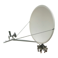
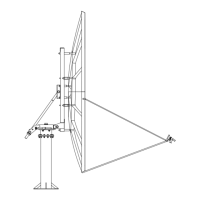
This document describes the installation kit for a Prodelin 3.8 meter antenna, Model 1381, which is designed to interface with an RC2000C AZ/EL antenna controller. The kit includes various components for connecting the interface box to the antenna's motors, sensors, and limit switches.

Function Description

The Prodelin 3.8 meter antenna installation kit provides the necessary components and instructions to connect a Prodelin 3.8 meter antenna (Model 1381) to an RC2000C AZ/EL antenna controller. This setup enables automated control of the antenna's azimuth and elevation movements. The kit facilitates the physical and electrical connections between the antenna's motors, sensors, and limit switches, and the interface box, which then communicates with the RC2000 controller. The RC2000 controller manages the antenna's movements, including auto-move algorithms and tracking functions, based on configured parameters.

Important Technical Specifications

RC2000 Controller:

  • Power: Can be powered by either 110 or 220/240 VAC.
  • AGC Input: Requires an analog voltage input proportional to satellite signal strength (0 to 10 volts). It can accept two channels of AGC signal strength information with adjustable gain and offset pots.
  • Mounting: Designed for rack mounting indoors.

Interconnect Cable (RC2000 to Interface Box):

  • Type: Belden 1083A cable (or similar, e.g., Olympic Wire and Cable Corp. part number 9883) is recommended.
  • Composition: Consists of 4 individually shielded triples (or triads).
  • Conductor Size: 20 AWG.
  • Shielding: Shields are equipped with a drain wire.
  • Voltage: Carries DC voltages of 40 volts or less.
  • Alternative: Satellite TVRO 'actuator cables' (16 AWG unshielded conductors, shielded 22 AWG triple with drain wire) can also be used.
  • Installation: Direct burial type cable can be used in the US.

Conduit Runs (Interface Box to Antenna Components): The installation kit includes steel-reinforced liquid-tight flexible conduit and cabling.

  • Azimuth Motor:
    • Conduit Length: 130 Inches
    • Cable Type/Length: 16/3 - 140 Inches
    • Fittings: Straight fitting at interface box, 90 Degree Fitting at azimuth motor.
  • Azimuth Sensor:
    • Conduit Length: 113 Inches
    • Cable Type/Length: 18/2 - 170 Inches, Belden 8772 - 124 Inches
    • Fittings: Straight fitting at interface box, 45 Degree Fitting at azimuth sensor.
  • Azimuth Limit Switch:
    • Conduit Length: 31 Inches
    • Cable Type/Length: Continuation of 18/2 Cable
    • Fittings: 90 Degree Fitting at azimuth sensor, Straight Fitting at azimuth limit switch (requires 1/2" to 3/4" conduit bushing).
  • Elevation Sensor:
    • Conduit Length: 120 Inches
    • Cable Type/Length: 18/2 - 160 Inches, Belden 8772 - 130 Inches
    • Fittings: Straight fitting at interface box, 90 Degree Fitting at elevation sensor.
  • Elevation Limit Switch:
    • Conduit Length: 12 1/2 Inches
    • Cable Type/Length: Continuation of 18/2 Cable
    • Fittings: 90 Degree Fitting at elevation sensor, 90 Degree Fitting at elevation limit switch (requires 1/2" to 3/4" conduit bushing).
  • Elevation Motor:
    • Conduit Length: 105 Inches
    • Cable Type/Length: 16/3 - 120 Inches
    • Fittings: Straight fitting at interface box, 90 Degree Fitting at elevation motor.

RC2000 Software Configuration (for Prodelin 3.8 meter antenna, Model 1381):

  • AutoPol Enable: 0 - DISABLE (AutoPol disabled).
  • Simultaneous Az/El Enable: 0 - DISABLE (RC2K90INT-1 does not support simultaneous azimuth and elevation movement).
  • Azim Slow Speed: 254 (Disables pulse width modulation based slow speed system).
  • Elev Slow Speed: 254 (Disables pulse width modulation based slow speed system).
  • Rotating Feed Present: 0 - NO (Assumes a 3-wire servo type polarization control device or no device).
  • Az/El Drive Options Enable: 1 - ENABLE (Enables access to various drive-related CONFIG mode items).
  • Az/El Auto Retry: 2 (Controller makes 2 attempts to reach target position).
  • Az/El Fast Deadband: 4000 milliseconds (Antenna coasts for 4 seconds; 4001 disables count accumulation if not commanded to move).
  • Az/El Slow Deadband: 4023 milliseconds (Antenna coasts for 4 seconds; '23' prevents peakup scheduling within 230 seconds of a program track table entry).
  • Azim Coast Threshold and Elev Coast Threshold: 14 position counts (Motors turn off 14 counts from target position).
  • Azim Max Position Error and Elev Max Position Error: 8 position counts (Controller initiates auto move if resting position is > 8 counts from target).
  • Antenna Size: 380 centimeters.
  • Azim Constant: 17492 counts per radian (305 azimuth position counts per degree).
  • Elev Constant: 33615 counts per radian (587 elevation position counts per degree).
  • Max Track Error: 5 tenths of a dB.
  • Search Enable: 0 - DISABLE (Disabled for transmit applications).

Usage Features

Installation Process:

  1. AC Power: Ensure fused AC power with a local disconnect is present at the antenna pad, conforming to NEC and other applicable codes. The user is responsible for routing AC power to the interface box.
  2. Interconnect Cable: Obtain and route the RC2000 to interface box interconnect cable.
  3. Conduit Attachment: The antenna is shipped with four flexible conduit runs (with wire pulled through) for the elevation motor, elevation sensor, azimuth sensor, and azimuth motor, already attached to the interface box. The installer must attach these runs to their respective components. Two additional conduit runs (elevation sensor to elevation limit switch, and azimuth sensor to azimuth limit switch) are included with the interface box but not attached; the installer must place these. Teflon tape is included for fittings that cannot accept a sealing gasket or O-ring.
  4. Wiring Connections:
    • Install the RC2000 to Interface Box Interconnect cable, making connections at the RC2000 (refer to RC2000 manual Chapter 3).
    • Attach motor control signals (AZ1_CTL, AZ2_CTL, EL1_CTL, EL2_CTL) from the interconnect cable to the circuit board in the interface box.
    • Splice sensor cables from the interconnect cable to the Belden 8772 cable in the interface box using 3M Scotchlok connectors (refer to RC2K90INT-1 manual Figure 7). Proper sensor connection is critical.
    • Connect sensor cables to the sensors (refer to Figure P1). Cut off the drain wire and use heat shrink tubing over the cut insulation to prevent contact with the sensor housing.
    • Connect 16/3 cables to motor lead wires (A1, A2, green ground wire) at azimuth and elevation motor terminal boxes using butt-type crimp connectors (refer to Figure P1).
    • Connect 18/2 cables to limit switches at azimuth and elevation limit switches, installing diodes and jumpers, using spaded terminals (refer to Figure P2).
  5. AC Power Connection: Once all connections are complete, connect the interface box to AC power.
  6. Software Configuration: Configure the RC2000 controller using the provided CONFIG mode item values to ensure proper operation with the Prodelin 3.8 meter antenna. This includes disabling AutoPol and simultaneous Az/El movement, setting slow speeds, and defining antenna parameters.

Cable Management:

  • Always use shielded cables for sensors.
  • Connect the shield drain wire only at the RC2000.
  • If splicing cables, ensure the drain wire is also spliced.
  • Prevent shield or drain wire contact with ground. Use heat shrink over frayed shields.

Maintenance Features

Troubleshooting:

  • RUNAWAY errors: If these occur, the Az/El Fast Deadband parameter can be set to 4001 to disable the accumulation of counts when the antenna is not commanded to move or is not coasting to a stop.
  • "Holes" in program track table: The Az/El Slow Deadband parameter (4023 milliseconds) helps prevent this by controlling peakup scheduling.
  • Position Error: The Azim Max Position Error and Elev Max Position Error parameters (8 position counts) define when the controller initiates an auto move to correct position discrepancies.

Component Replacement: The Bill of Materials lists various components, including fuses, connectors, cables, and diodes, which may be replaced as needed.

  • Fuses: 12 Amp Ceramic AC Line Fuse (Littlefuse 314 012) and 8 Amp Ceramic Armature Fuse (Littlefuse 314 008) are specified.
  • Resistor: A 0.025 ohm Plug-In Horsepower Resistor (KB Electronics, Inc. 9841) is used for KBPB-225 Motor Drive Modules.

Tools Required for Installation (and likely maintenance):

  • Wiring tools: wire cutters, wire stripper, crimp connector crimp tool.
  • Heat gun or lighter (for heat shrink tubing).
  • Hack saw (for cutting liquid tight steel reinforced conduit).
  • Fine straight bladed screwdriver (for AGC GAIN and OFFSET pots, and screw terminals).
  • Phillips and straight bladed screwdrivers (for accessing interface box, terminal boxes).
  • 12" Crescent wrench (for conduit fittings).
  • Channel Lock pliers and regular pliers (for 3M Scotchlok connectors).

Documentation: The manual emphasizes referring to the RC2000 manual for additional information on connections and troubleshooting, and to figures P1 and P2 for wiring diagrams.

prodelin 1381 Specifications

General IconGeneral
Brandprodelin
Model1381
CategoryAntenna
LanguageEnglish

Related product manuals