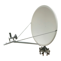
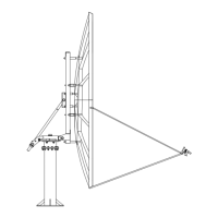
Prodelin 3.8m Antenna Installation Kit
does not come in contact with the sensor housing. Use the 3M Scotchlok connectors to make the
connections.
5. At the azimuth and elevation motor terminal boxes, connect the 16/3 cables to the motor lead wires
(refer to figure P1). Use the butt type crimp connectors to make the connections. The motor input
leads are labeled A1 and A2. The green wire is the motor ground wire.
6. At the azimuth and elevation limit switches connect the 18/2 cables to the limit switches (refer to
figure P2). The diodes and the jumper should be installed. Use the spaded terminals for these
connections.
4