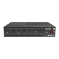
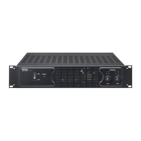
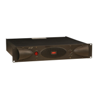
8
ENG ITA
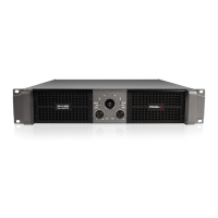
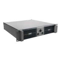
PANNELLO FRONTALE
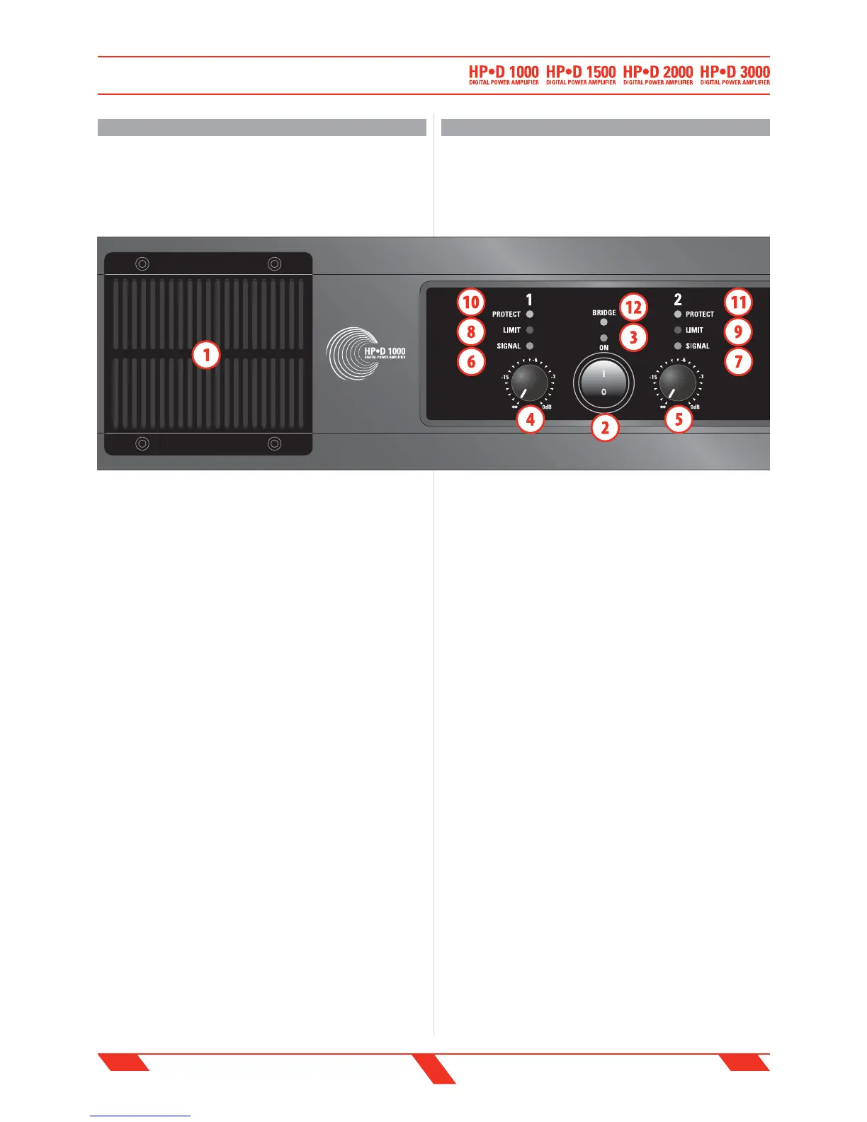
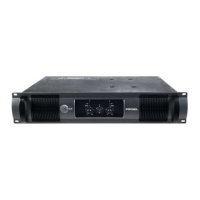
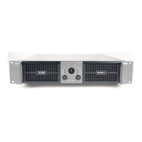
NOTA: Gli ampli catori HPD2000 e HPD3000 sono rispettivamente
le doppie versioni degli amplificatori HPD1000 e HPD1500,
quindi le istruzioni per i canali 3 e 4 sono le stesse dei canali 1 e
2 rispettivamente (vedi anche entrambe le figure dei pannelli
frontali).
1. Apertura per aria di ra redamento
Apertura rimovibile per l'aria: mantenerla sempre pulita dalla polvere.
2. Interuttore accensione
L'ampli catore è acceso "ON" quando l'interruttore è nella posizione "I".
3. Indicatore di accensione
LED blu: quando acceso indica che l'amplificatore è stato acceso e
l'alimentazione AC è disponibile.
4. Controllo di Livello Canale 1
Controllo di livello rotativo a scatti: in modalità STEREO e PARALLEL
attenua il livello del segnale inviato al canale 1 dell'ampli catore, o in
modalità BRIDGE agisce come singolo controllo per attenuare il livello
del segnale inviato a entrambi i canali.
L' attenuazione varia tra completamente chiuso “∞” a completamente
aperto “0” o livello nominale (il segnale non è attenuato in nessun modo,
viene inviato al canale dell'ampli catore allo stesso livello con cui arriva
all'ingresso).
5. Level control Channel 2
Controllo di livello rotativo a scatti: in modalità STEREO e PARALLEL
attenua il livello del segnale inviato al canale 2 dell'ampli catore, in
modalità BRIDGE non ha alcun e etto.
L' attenuazione varia tra completamente chiuso “∞” a completamente
aperto “0” o livello nominale (il segnale non è attenuato in nessun modo,
viene inviato al canale dell'ampli catore allo stesso livello con cui arriva
all'ingresso).
6. Indicatore di segnale (SIGNAL) del Canale 1
LED verde che si accende per indicare la presenza del segnale sull'uscita
del canale 1.
7. Indicatore di segnale (SIGNAL) del Canale 2
LED verde che si accende per indicare la presenza del segnale sull'uscita
del canale 2.
FRONT PANEL
NOTE: The HPD2000 and HPD3000 amplifiers are respectively
the double versions of HPD1000 and HPD1500 ampli ers, so the
instructions for channels 3 and 4 are the same of channels 1 and 2
respectively (see also both front panel gures).
1. Cooling vent
Removable cooling vent: always keep it clean from dust.
2. Power switch
Ampli er is "ON" when the switch is in the "I" position.
3. Power indicator
Blue LED: when lighted indicates ampli er has been turned on and AC
power is available.
4. Level control Channel 1
Rotary detented level control: in STEREO and PARALLEL operation it
attenuates the level of the signal sent to the channel 1 of the ampli er,
while in BRIDGE operation it operates as single control to attenuate the
level of the signal sent to both the channels.
The attenuation ranges from “∞” fully closed (the signal is completely
attenuated) to “0” fully open, nominal level (the signal is not attenuated
in any way, so is fed to the ampli er channel at the same level at which
it arrives on input).
5. Level control Channel 2
Rotary detented level control: in STEREO and PARALLEL operation it
attenuates the level of the signal sent to the channel 2 of the ampli er.
In BRIDGE operation it doesn't work.
The attenuation ranges from “∞” fully closed (the signal is completely
attenuated) to “0” fully open, nominal level (the signal is not attenuated
in any way, so is fed to the ampli er channel at the same level at which
it arrives on input).
6. Channel 1 SIGNAL indicator
Green LED illuminates to indicate the presence of the signal at the
ampli er channel 1 output.
7. Channel 2 SIGNAL indicator
Green LED illuminates to indicate the presence of the signal at the
ampli er channel 2 output.
FRONT PANEL
PANNELLO FRONTALE

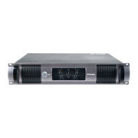

 To Next Page