Do you have a question about the PROEL M-20 and is the answer not in the manual?
Read safety instructions carefully before use. Keep away from water and heat.
Explains symbols for dangerous voltage and important instructions.
Warns about potential hearing loss from high sound levels and provides OSHA limits.
Procedures for product inspection by qualified personnel for defects, liquid ingress, or damage.
Details the two-year warranty and procedures for returning defective products.
Step-by-step guide to get sound through the mixer immediately.
Instructions on adjusting GAIN controls for optimal internal levels.
Steps for connecting instruments, adjusting levels, and creating a mix.
How the gain control adjusts input sensitivity for mic and line inputs.
Details the High, Mid, Frequency, and Low EQ controls for tone shaping.
Explains how AUX send controls route signals to outputs and effects.
Explains the PEAK LED for clipping detection and SOLO activation.
How to use the SOLO switch for pre-fader or post-fader listening.
Adjusts input sensitivity for mic and line inputs on stereo channels.
Details the EQ controls for tone shaping on stereo channels.
Sends signal to AUX 3 and internal FX1 (post-fader).
Sends signal to AUX 4 and internal FX2 (post-fader).
Explains PEAK LED for clipping and SOLO function on stereo channels.
How to use the SOLO switch for pre/post-fader listening on stereo channels.
Detailed descriptions of various reverb, delay, and modulation effects.
Details specific effects like TAP DELAY, CHORUS, FLANGER, and their variations.
How to set delay time using the TAP button and its indicator LED.
Controls for adjusting signal levels sent to internal effects FX1 and FX2.
LEDs indicating clipping and SOLO status for FX1 and FX2.
Allows selection between pre-fader (PFL) and post-fader (AFL) listening.
Describes the USB port for audio exchange and use as a soundcard.
Explains how the USB port sends/receives stereo audio data between mixer and computer.
Instructions for connecting and setting up the M20USB on Windows systems.
Instructions for connecting and setting up the M20USB on Macintosh OS X.
Detailed guide for setting up M20USB for DAW recording and monitoring.
Checks for power connection problems and outlet issues.
Troubleshooting steps for channels with no signal output.
Tips for identifying and reducing noise or hum, including grounding and USB interference.
Illustrates how to connect drum kits, guitars, keyboards, recorders, amps, and monitors.
Illustrates the signal path for various inputs, EQ, and sends.
Illustrates signal paths for main, group, phones, and C.ROOM outputs.
Illustrates signal paths for AUX sends and digital effect processors.
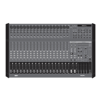
| Channels | 20 |
|---|---|
| Inputs | 20 |
| Phantom Power | Yes |
| Type | Analog |
| EQ | 3-band |
| Aux Sends | 4 |
| Subgroups | 4 |
| Effects | Built-in effects |
| Outputs | Control Room |