Do you have a question about the Profile PIN-116 and is the answer not in the manual?
Liquid Crystal Display screen for showing measurements and status.
Selects measurement modes (V DC, V AC, Ω, etc.).
Standard connection point for the black test lead.
Dedicated input for high current measurements up to 10A.
Standard connection point for the red test lead for most measurements.
Freezes the current reading on the display.
Illuminates the display for better visibility in low light.
Indicates a low resistance connection, often with an audible beep.
Indicates that the battery is nearly empty and needs replacement.
Symbol for diode testing function.
Symbols representing Alternating and Direct current or voltage.
Symbols for Micro (μ), Milli (m), and Kilo (k) for current/resistance.
Symbol for Ohm (Ω), the unit of electrical resistance.
Crucial safety warning for high voltage measurements.
Metre automatically turns off after 15 minutes of inactivity.
Indicates the measured value exceeds the selected range.
Explains varying readings when no circuit is connected.
Safety caution regarding voltage peaks from motors.
Procedure for measuring DC voltage using the multimeter.
Safety caution regarding voltage peaks from motors.
Procedure for measuring AC voltage using the multimeter.
Safety warning for resistance measurements and capacitor discharge.
Procedure for measuring resistance, including circuit isolation.
Safety warning against measuring live circuits or wires.
Procedure for checking continuity of wires or circuits.
Safety warning against testing live diodes.
Procedure for testing diodes, including voltage and polarity.
Safety warning for AC current measurements above 250V AC.
Caution about exceeding 30 seconds for 10A current measurements.
Procedure for measuring AC and DC current intensities.
Safety warning to disconnect probes before temperature measurement.
Procedure for measuring temperature in Celsius or Fahrenheit.
Safety warning to disconnect wires before opening the battery compartment.
Steps to replace the battery, including compartment access.
Safety warning to disconnect wires before opening the fuse compartment.
Steps to replace the fuse, including compartment access and specifications.
Specifies the safety rating for overvoltage conditions (CATII).
Details of the display, including count and polarity indication.
Range, resolution, and accuracy for DC voltage measurements.
Range, resolution, and accuracy for AC voltage measurements.
Range, resolution, and accuracy for DC current measurements.
Range, resolution, and accuracy for resistance measurements.
Range and resolution for temperature measurements in °C and °F.
Details for diode testing, including test current and voltage.
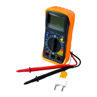
This document describes the Profile PIN-116 Multimeter, a device designed for measuring various electrical parameters. It provides instructions for its operation, usage features, and maintenance.
The Profile PIN-116 Multimeter is a versatile tool capable of measuring DC voltage, AC voltage, resistance, AC/DC current intensity, and temperature. It features an LCD display for showing measurement readings, a function switch to select the desired measurement mode, and input connections for test leads. The device also includes a HOLD button to freeze the current display value and a background lighting feature for improved visibility in low-light conditions. An auto-power-off function is integrated to conserve battery life, switching off the meter after 15 minutes of inactivity.
Before any measurement, it is crucial to switch the function switch to the OFF position when the meter is not in use. If the display shows "1" during a measurement, it indicates that the value exceeds the selected range, and a higher range should be chosen. For low AC and DC ranges, the display might show a random, varying measured value even without connected test wires due to high input sensitivity; this is normal, and the reading will stabilize upon connection to a circuit.
To measure DC voltage, set the function switch to the V DC position. Insert the black test lead into the negative (3)COM connection and the red test lead into the positive (5)V connection (or the 10A connection for measurements of 10A or lower). Touch the circuit with the test probes, ensuring correct polarity (red to positive, black to negative). The display will show the voltage, and a negative sign (-) will appear if the polarity is reversed. A critical caution is to avoid measuring DC voltages when a motor in the circuit is switching ON or OFF, as this can generate large voltage peaks that may damage the meter.
For AC voltage measurements, switch the function switch to the V AC position. Connect the black test lead to the negative (3)COM connection and the red test lead to the positive (5)V connection. Touch the circuit with the test probes to read the AC voltage on the display. Similar to DC voltage, avoid measuring AC voltages when a motor in the circuit is switching ON or OFF to prevent damage from voltage peaks.
To measure resistance, set the function switch to the Ω position. Insert the black test lead into the negative (3)COM connection and the red test lead into the positive (5) connection. Touch the circuit or part to be tested with the test probes. For accurate readings, it is recommended to disconnect one side of the component from the circuit to prevent interference. A crucial warning for resistance measurements is to cut the power supply to the unit under test and discharge all capacitors before proceeding to prevent electric shocks. Additionally, remove batteries and unplug the unit from the socket.
To check for continuity, switch the function switch to the continuity position. Insert the black test lead into the negative (3)COM connection and the red test lead into the positive + (5) connection (Ω). Touch the circuit or wire with the test probes. An acoustic signal will sound if the resistance is lower than approximately 100 Ω, and the display will also show the actual resistance. A warning is issued to never measure connections with live circuits or wires to avoid electric shocks.
For diode testing, set the switch to the diode symbol position. Insert the black measuring cable into the negative (3) (COM) input and the red measuring cable into the positive diode input (5). Place the measuring heads on the diode. The conductor voltage will be displayed, typically between 400 to 700mV. A "1" indicates reverse voltage, while a short-circuit appliance shows a result close to 0 mV. An open appliance will also show "1" for both poles. A warning advises against testing live diodes to prevent electric shocks.
To measure current intensity, insert the black test lead into the negative (1)COM connection. For DC current up to 200 mA, set the function switch to the highest DC mA position and insert the red measuring cable into the (mA) input. For DC current strengths of 10 A, set the function switch to 10A and insert the red measuring cable into the 10A input. Before measuring, switch off the voltage of the circuit, open the circuit at the desired measurement point, and then touch the negative side with the black test probe and the positive side with the red test probe. After connecting, restore power to the circuit and read the current intensity from the display. A warning states that AC current intensities should not be measured in circuits with a voltage over 250V AC. Additionally, a caution advises against conducting current measurements in the 10A range for longer than 30 seconds, as this can damage the meter or testing wires.
To measure temperature, switch the function switch to either the °F (Fahrenheit) or °C (Celsius) position. Insert the banana plug of the thermocouple probe into the negative (3)COM connection and the red wire into the positive (5) Temp diode connection. Touch the part to be measured with the end of the temperature probe and hold it until the measured value stabilizes (approximately 30 seconds). The digital display will show the temperature. A warning emphasizes disconnecting both test probes from any power sources before measuring temperature to prevent electric shocks. Another warning reminds users to ensure the thermocouple has been removed before proceeding with other measurements.
To switch the display background lighting on or off, press the (7) key for more than 1 second. The background lighting will automatically switch off after 10 seconds.
The HOLD function allows you to freeze the current value on the display. Briefly press the HOLD key (6) to activate this function and press it again briefly to deactivate it.
When the batteries are nearly empty, the message "BAT" will appear on the right side of the display, indicating that the battery needs replacement. To replace the battery, first disconnect the meter's testing wires and remove the rubber housing. Open the battery cover by removing the screw with a screwdriver. Place the new battery in the compartment, ensuring correct polarity. Replace the battery cover and fasten it with the two screws. Dispose of old batteries at a collection point. A critical warning states that the meter should not be used until the battery compartment cover has been replaced and fastened, to prevent electric shocks. If the meter is not functioning properly after battery replacement, check the fusing and the battery to ensure they are in working order and correctly fitted.
To replace the fusing, disconnect the testing wires from the meter and any items being tested. Remove the rubber housing. Open the fusing compartment cover by removing the screw. Carefully pull out the old fusing from the compartment. Place the new fusing in the holder, ensuring it is of the correct size and specification (10A/250V fast-reacting for the 10A range). Replace the fusing cover, insert the screw, and tighten firmly. A warning states that the meter should not be used until the fuse compartment cover has been replaced and fastened, to prevent electric shocks.
| Display Type | LCD |
|---|---|
| DC Current Ranges | 200µA, 2mA, 20mA, 200mA, 10A |
| Diode Test | Yes |
| Continuity Test | Yes |
| Power Supply | 9V battery |
| AC Voltage Ranges | 200V |
| Resistance Ranges | 200Ω, 2kΩ, 20kΩ, 200kΩ, 2MΩ |
| Battery Type | 6F22 |
| Weight | 150g (with battery) |
| Display Digits | 3.5 digits (1999 counts) |
| DC Voltage Ranges | 200mV, 2V, 20V, 200V |