lOcatiOn
Select a location where a water leak will not cause
property damage and provides adequate means for water
drainage. This well tank and the associated piping may in
time leak. The manufacturer is not responsible for any
water damage that may occur in association with the well
tank installation. The tank location should be as close as
possible to the system pressure switch to reduce the
negative effects of friction/elevation pressure loss. This
tank has been designed to be mounted on a level surface
and must be adequately supported around the entire base.
Disconnect or shut off the
electrical power source to the
system pump. Shut off the water supply to the
system and remove all water pressure from the
system. Failure to follow these instructions may result in
serious injury or death and or property damage.
Install the well tank in the incoming water line from the
pump and before any fixtures (see Fig. 1). Adequate
thread sealant (pipe dope) must be added to ensure a
leak free installation.
A properly sized pressure
relief valve set at a maximum o f
100 psi must be installed in the system.
Before turning on the water supply to the system, open
a water faucet to allow air from the system piping to be
released. Turn on the power to the water supply and the
pump should turn on, filling the system piping. When the
water is flowing freely from the faucet without air, close
the faucet. The pump will continue to run filling the well
tank. Inspect the installation for water leaks paying close
attention to the connection between the well tank and the
system piping.
be f O r e in s t a l l a t i O n
in s t a l l a t i O n
pre-charge adjustment
This well tank is shipped from the factory with a pre-charge of 38 psi. The well tank should be pre-charged to 2 PSI below
the cut-in setting of the pressure switch but must not exceed 80 psi. Any adjustments to the factory pre-charge must be
done prior to initial tank installation and with 0 psi pressure on the system.. DO NOT ADJUST THE PRE-CHARGE OF THE
EXPANSION TANK WITH THE SYSTEM UNDER PRESSURE!
tO adjust tank precharge (Prior to Installation)
Remove the protective cap from the air valve.
Check the tank pre-charge pressure using a standard tire pressure gauge.
If required add air to the tank using a manual bicycle tire pump until the proper pre-charge pressure is reached.
Replace the protective cap on the air valve.
tO adjust tank precharge (After Installation)
Disconnect power to the system pump.
Drain the tank of water by opening a faucet
Add or release air as required (see above)
Do not adjust the tank air pressure if there are any visible signs of corrosion on the tank. If this well tank shows any visible signs
of corrosion or rusting, the tank must be replaced immediately. Failure to follow these instructions may result in serious injury
or death and or property damage.
WARNING
WARNING
WARNING
typical installatiOn
fig. #1
Pressure
Switch
Pressure
Gauge
Pressure
Relief Valve
(required)
(2)
en t r e t i e n
Faire vérifier ce réservoir de puits et le système au complet par un professionnel qualifié tous les ans.
Examiner visuellement le réservoir et son raccord aux tuyaux du système pour déceler des signes de fuites d’eau ou de corrosion à l’extérieur
du réservoir ou du raccord.
Si le réservoir de ce système d’eau présente des signes visibles de fuite, de corrosion ou de rouille, il faut
le remplacer immédiatement pour éviter les blessures et dommages matériels. Ne pas régler la pression
d’air du réservoir s’il y a des signes de corrosion sur le réservoir. Le non-respect de ces instructions peut entraîner des blessures graves ou
la mort, ou encore des dommages matériels.
installatiOn de plusieurs réservOirs
MATÉRIAUX DE CONSTRUCTION
Réservoir : Acier laminé à froid
Fini : Peinture de qualité d’appareil électroménager pour une installation tant à
l’intérieur qu’à l’extérieur
Chambre d’eau : Caoutchouc butyle à 100 %, revêtu de polypropylène
Raccord : Acier
Essais : Haute pression, soudage à la molette, hélium,
vérification finale de la précharge
Reniflard : En laiton avec joint torique
Garantie : Cinq (5) ans
Tous les réservoirs doivent avoir la même précharge pour que le
système puisse fonctionner correctement. Ajuster la précharge de
chaque réservoir selon les indications de la page 2. Le manostat ou
la commande du système doit se trouver au centre (voir le schéma)
pour que les réservoirs puissent fonctionner
correctement.
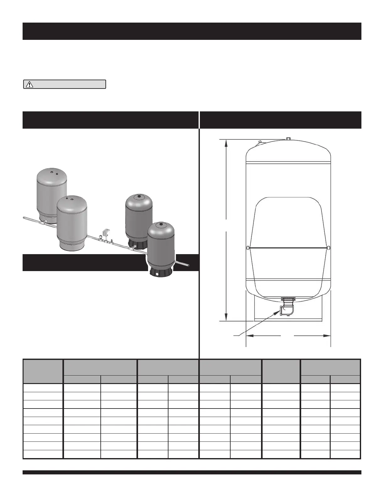
DIMENSIONS ET CAPACITÉS
Pression maximale de service : 125 lb/po². Température maximale de service, interne et externe : 140
o
F. Précharge du réservoir : 38 lb/po2 (mano).
spécificatiOns/dimensiOns
(11)
MISE EN GARDE
A
B
C
Volume Total A B C Poids Total
Du Réservoir
Hauteur
Diamètre
Raccord
gal liters po cm po cm lb kg
20
26
32
33,4
44
62
81
85
119
PFX20S
PFX26S
PFX32S
PFX33S
PFX44S
PFX62S
PFX81S
PFX86S
PFX119S
80
100
120
130
170
240
310
325
450
29
34,5
27,75
42,75
36,25
48
62
44,5
59,75
73,66
87,63
70,48
108,58
92,07
121,92
157,48
113,03
150,49
40,64
40,64
53,34
40,64
53,34
53,34
53,34
66,04
66,04
1 po NPT
1 po NPT
1 1/4 po NPT
1 po NPT
1 1/4 po NPT
1 1/4 po NPT
1 1/4 po NPT
1 1/4 po NPT
1 1/4 po NPT
36,0
41,0
54,0
49,0
67,0
82,0
99,0
121,0
153,0
16,3
18,6
24,5
22,2
30,4
37,2
44,9
54,9
69,5
16
16
21
16
21
21
21
26
26
Modèle
.
.
.
.
.
.
.
 Loading...