2
Consult a licensed electrician or RV technician for installation assistance 814420 Rev. C
WARNING: FIRE HAZARD
DC Input wiring must be protected with properly sized circuit protec-
tion (fuses or circuit breakers)
Never operate the inverter without properly connecting the equipment
ground.
Tighten the nuts on terminals properly. Loose connections cause exces-
sive voltage drop and may cause overheated wires and melted insula-
tion. DO NOT under tighten the screw on the terminal lugs. This will
cause the wires to lose connection.
Failure to follow these instructions may result in serious injury or
death. Failure to follow these instructions may also damage the
unit and/or equipment.
Mounting Instructions
WARNING: FIRE, SHOCK, AND ENERGY HAZARD
Inverter should only be installed by an electrician or a certified RV
technician.
Inverter is NOT ignition protected. Do not mount in the LP gas or bat-
tery compartments
Inverter should be mounted in a dry, well ventilated space with ade-
quate air flow
Failure to follow these instructions may result in serious injury or
death. Failure to follow these instructions may also damage the unit
and/or equipment.
Mounting Instructions
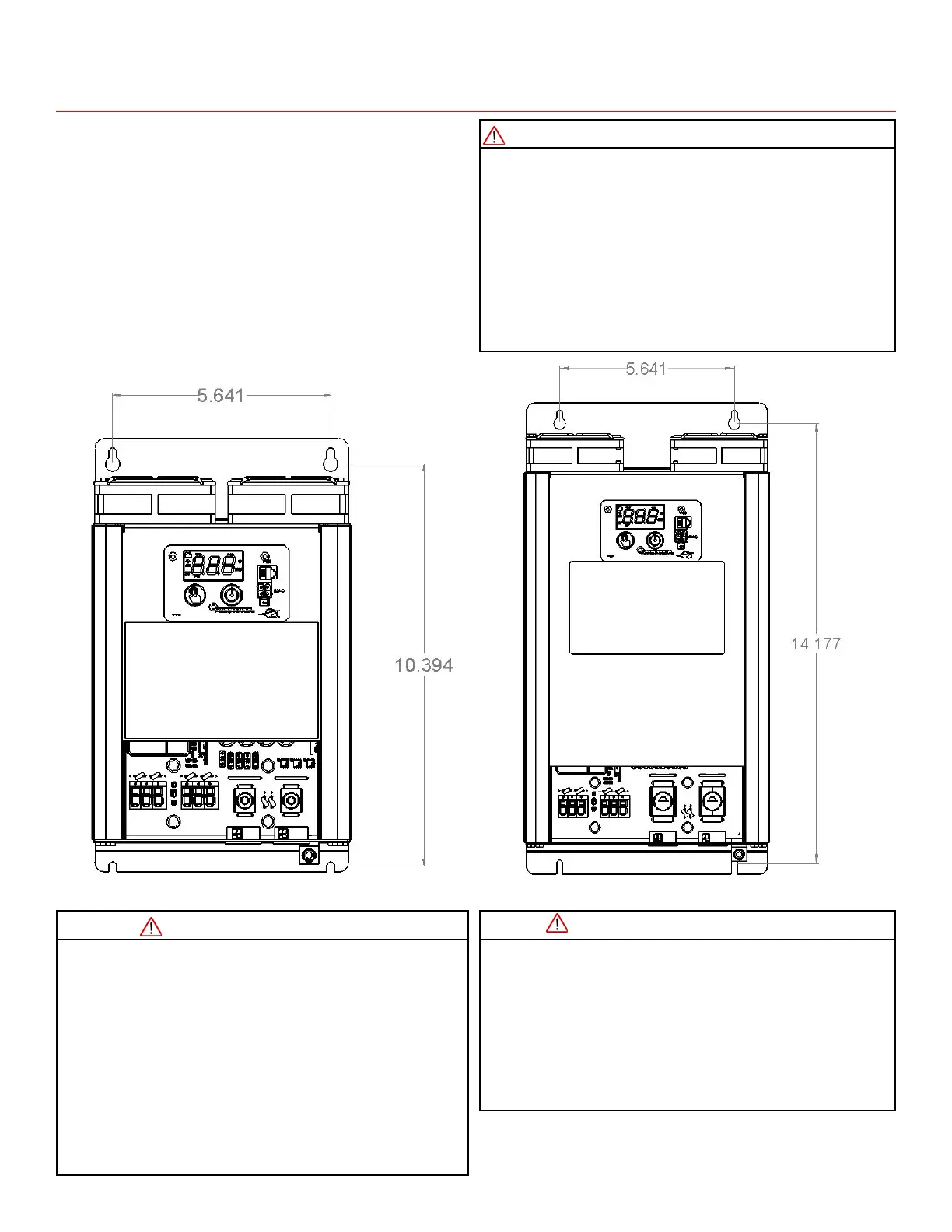
Inverter may be installed horizontally or vertically. Vertical
installations should be sure to protect the inverter from for-
eign debris falling inside the unit through the ventilation
slots.
External strain relief should be used for DC input wires.
Inverter can be secured to a flat surface using the side
mounting slots. See Figure1 and Figure 2 for mounting hole
pattern.
Inverter should be located in a well ventilated compartment.
Minimum compartment dimensions provide 2” of space
above the inverter display and open on the electrical connec-
tion side. Operation in high ambient temperatures require
additional ventilation space.
NOTICE: EQUIPMENT DAMAGE
Do not connect any AC source (such as generator or utility power) to
the AC output wiring of the inverter. Connecting an AC source to the
AC Output of the inverter will result in hazardous conditions.
DO NOT disassemble the inverter. It does not contain any user service-
able parts. Attempting to service the unit yourself could result in an
electrical shock or burn.
Failure to follow these instructions may damage the unit and/or
equipment.
Figure 1: PD1610 Mounting Hole Pattern Figure 2: PD1618/PD1620 Mounting Hole Pattern
 Loading...