EasyManua.ls Logo

Progressive Dynamics PD1610 - User Manual

Progressive Dynamics PD1610
18 pages
Print Icon
To Next Page IconTo Next Page
Loading...
Installation and Operation Guide for
PD1600 Series Pure Sine Wave Inverters
© 2022 Progressive Dynamics Enterprises, LLC. All rights reserved.
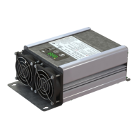
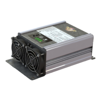
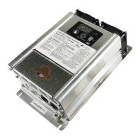
The PD1600 Series Inverters are 120 VAC, 60 Hz, pure sine wave inverters with integrated transfer switch. Available in 1000W, 1800W,
and 2000W models, the PD1600 series inverters have been robustly designed with safety and protection features for installation in recrea-
tional and commercial vehicles. With a built in transfer switch, this inverter can switch seamlessly between inverter power and external
shore power without any power interruptions. It has been UL458 certified in both the US and Canada, so you can feel comfortable knowing
that your inverter is safe.
With the recreational and commercial vehicle industry in mind, the PD1600 series inverter was designed to be compact and light-weight to
fit the strict size and weight constraints often found within these vehicles. The improved thermal design reduces the ventilation space re-
quired, which contributes to an even smaller space requirement for your inverter.
Progressive Dynamics, Inc. has a complete line of power products for your commercial and recreational vehicle needs. PDI has existing
product lines of power converters, automatic transfer switches, AC distribution panels, and DC distribution panels. These product lines,
along with the newly introduced inverters, make Progressive Dynamics the only part supplier you need to build a complete power system
for your recreational or commercial vehicle. Our experienced sales and service department are available to help determine which power
solutions are best suited to your needs.
701580H
Member

Other manuals for Progressive Dynamics PD1610

Questions and Answers

Progressive Dynamics PD1610 Specifications

General IconGeneral
BrandProgressive Dynamics
ModelPD1610
CategoryInverter
LanguageEnglish

Summary

Limited Warranty

Limited Warranty Statement

Progressive Dynamics warrants inverters against defects in material or workmanship under normal use and service.

Warranty Duration and Validity

The warranty extends for two years within the continental United States and Canada from the original purchase date.

Warranty Exclusions

Lists conditions and damages not covered by the warranty, including misuse, unauthorized alterations, and incidental damages.

Proof of Purchase and Claim Procedure

Outlines requirements for warranty claims, including proof of purchase and detailed defect information submission.

PD1600 Series Components

Inverter Models

Details the available PD1600 series inverter models: PD1610 (1000W), PD1618 (1800W), and PD1620 (2000W).

Remote Displays

Describes the optional remote displays, PD1601-25 (25') and PD1601-50 (50'), for inverter monitoring and control.

Introduction and Component Overview

Key Features of the PD1600 Series Inverter

Power Output & Transfer Functionality

Features pure sine wave output, automatic transfer switch, and 2X peak power for inductive loads.

Installation & User Interface

Covers easy installation, optional remote display, hardwired AC output, and auto-restart after DC disconnect.

Safety & Protection Systems

Details comprehensive safety features including voltage, overload, short circuit, over-temperature protection, and reverse battery protection.

30 A RV Power System Wiring Diagram

50 A RV Power System Wiring Diagram

Choosing an Installation Location

Installation Location Requirements

Details environmental (dry, cool, ventilated) and proximity requirements for safe and optimal inverter installation.

Mounting Orientation and Safety

Advises on proper mounting orientation (horizontal/vertical) and highlights safety warnings regarding ignition protection and location.

Recommended GFCI Receptacles

Lists specific Ground-Fault-Circuit-Interrupter (GFCI) receptacles recommended for use with PD1600 series inverters.

Mounting Instructions

General Mounting Procedures

Outlines steps for removing, positioning, and securing the inverter, including using it as a drill guide.

Vertical vs. Horizontal Mounting

Provides specific guidance for vertical mounting, including orientation and debris prevention, and recommends horizontal mounting.

Electrical Connection Instructions

DC Wiring Requirements

Specifies wire length, size, strip length, and connection torque for DC input connections, supporting various battery types.

AC Wiring and Grounding

Details AC input/output wiring, strain relief installation, and equipment grounding procedures according to electrical codes.

Connection Safety Precautions

Emphasizes disconnecting power before wiring and following local/national electrical wiring codes for safety.

AC Strain Relief Types

Push-In Style Strain Relief

Describes the Halex #20515 push-in style strain relief, its material, and installation instructions.

Metal Clamp Style Strain Relief

Details the Halex #20570 metal clamp style strain relief, its material, and installation steps.

Push-In Style Plastic Clamp

Explains the Halex #27515 push-in style plastic clamp strain relief and its installation method.

Display Interface and Error Codes

Display Panel Features

Lists the functions of the display buttons (Power, Select) and indicators (Power, Fault, Shore, Low Bat Warning).

Error Code Descriptions

Explains various error codes (E-1 to E-7), their conditions, and general descriptions for troubleshooting.

Display Operation and States

DC Input Voltage Display

Describes how DC input voltage is displayed, including battery and volts indicators.

AC Output Voltage & Power Displays

Explains how AC output voltage and power are shown, noting availability only when the inverter supplies power.

Sleep Mode Functionality

Details the automatic sleep mode activation, dimming of indicators, and manual exit procedures.

Troubleshooting Guide

Fault Light and E-1 Error

Addresses flashing fault lights and E-1 errors (low input voltage), including charging and connection checks.

E-2 and E-3 Error Conditions

Covers E-2 (high input voltage) and E-3 (overload/peak power) errors, with restart and load management advice.

E-4 Over-Temperature Issues

Explains E-4 errors due to over-temperature, suggesting ventilation improvements and location adjustments.

Buzzing Sound

Clarifies that a buzzing sound during compressor startup is normal and temporary.

Technical Specifications

Physical Specifications

Provides dimensions, net weight, and output waveform for PD1610, PD1618, and PD1620 models.

Transfer Switch Specifications

Details transfer voltage, transfer time, and pass-through ampacity for the integrated transfer switch.

AC Output and DC Input Specs

Lists output voltage, continuous/peak power, frequency, efficiency, nominal voltage, and voltage protection thresholds.

RV-C Connectivity

RV-C Introduction

Introduces RV-C communication capability for the PD1600 series, its use in RV multiplexing systems, and current functionality.

RV-C Connectivity Details

Compatible RV-C Data Groups

Lists data groups, periodic send intervals, and descriptions for inverter status and configuration reporting.

Compatible RV-C Commands

Outlines commands for controlling the inverter, configuring settings, and performing general resets.

Related product manuals