8
ASSEMBLY INSTRUCTIONS
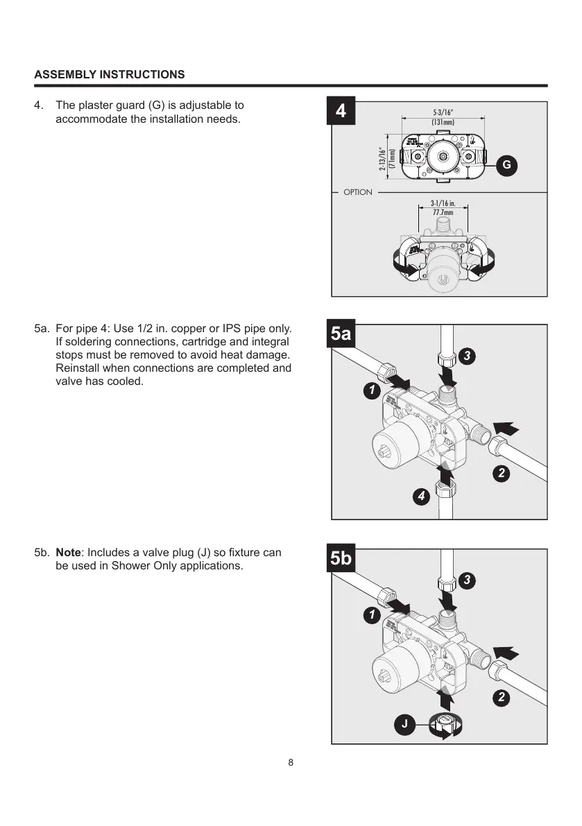
4. The plaster guard (G) is adjustable to
accommodate the installation needs.
5a. For pipe 4: Use 1/2 in. copper or IPS pipe only.
If soldering connections, cartridge and integral
stops must be removed to avoid heat damage.
Reinstall when connections are completed and
valve has cooled.
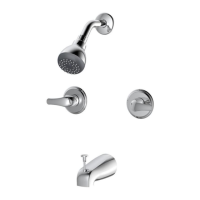
5b. Note: Includes a valve plug (J) so fixture can
be used in Shower Only applications.