BM500-BT
CONNECTORS AND TERMINALS
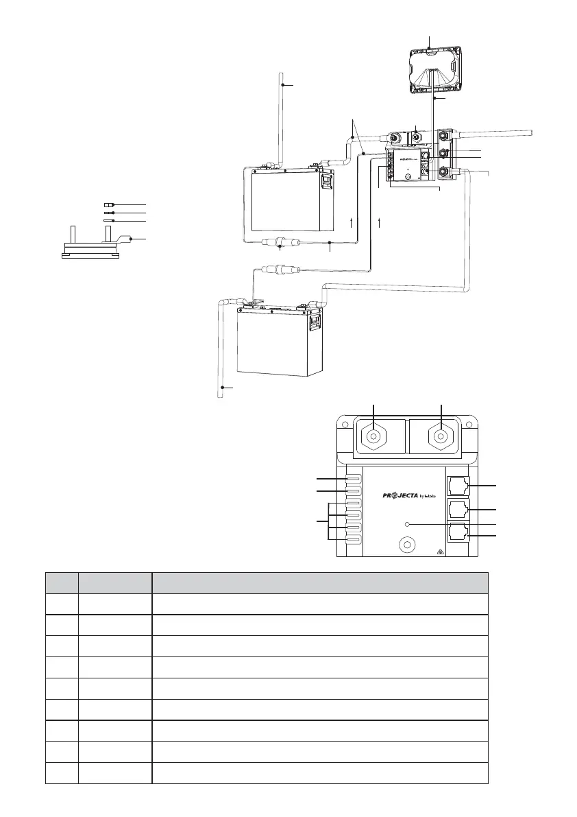
CONNECTION DIAGRAM FOR DUAL BATTERY SETUP
Table 1: Connectors and terminals of BM500-BT
①
③
⑥
②
④
⑤
⑦
⑧
⑨
NO. Print Description
LED indicator (See Chapter 2.3)
1 B-
2 S-
3 +B1
4 +B2
5 N/A
6 TEMP
7 DISPLAY
8 Status
9 COMM
Auxiliary battery negative input terminal
DC loads negative input terminal
Auxiliary battery positive input terminal (use supplied fused red cable)
Starter battery positive input terminal
Terminals not used
Temperature sensor cable input
Bluetooth™ battery monitor cable input
485 and CAN communication port (See Chapter 2.4)
B- S-
3
STATUS
DISPLAY
N/A
N/A
N/A
N/A
Brown & Watson
International Pty. Ltd.
Knoxfield, Victoria 3180
Australia
+
B1
+Service
Battery
B
-
Battery
Negative
Battery
S
-
Load/Charger
Negative
+
B2
+Starter
Battery
TEMP
COMM
Connect to
INTELLI-RV
GREEN: OK
RED ON: Over Current >500A
P/No. PMSHUNT 500A Current Shunt
• The nominal current for the dry contact
is 2A@30V or 0.5A@125V
• The battery temperature sensor should
be connected to the auxiliary battery
(any terminal)
• Please ensure the connection is
fastened as below picture
• Assembly sequence of nut,
washer and cable lug:
Auxiliary battery positive (to load)
Auxiliary battery
Nut
Spring washer
Washer
Cable lug
Starter battery
Starter battery positive
1A fuse
Supply cable (included)
Programmable
alarm contact
Spare Terminals
for future
expansion
+B1 +V2
Keep these cables
as short as possible
+
-
+
+
-
+
-
Bluetooth Battery Monitor
Battery negative
(system ground)
Ethernet cable
STATUS
DISPLAY
N/A
N/A
N/A
Brown & Watson
International Pty. Ltd.
Knoxfield, Victoria 3180
Australia
+
B1
+Service
Battery
B
-
Battery
Negative
Battery
S
-
Load/Charger
Negative
+
B2
+Starter
Battery
TEMP
COMM
Connect to
INTELLI-RV
GREEN: OK
RED ON: Over Current >500A
P/No. PMSHUNT
500A Current Shunt
AUX
Alarm
Additional
COMM port
for accessory
control
Temperature sensor input
Bus bar (optional, not included)