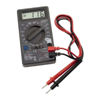
DIGITAL
MULTIMETER
P/No. DT830B
BATTERY & FUSE
The low battery symbol ‘ ‘ will be displayed when
the internal 9V battery is low (<7.5V), indicating that
the battery should now be replaced. If the meter does
not function on the DCA range, the internal 500mA
fuse may have blown. To replace the battery or fuse,
remove the test leads from the meter and remove the
two screws from the rear cover. Replace the battery
or fuse and then reassemble.
WARRANTY STATEMENT
Applicable only to product sold in Australia
Brown & Watson International Pty Ltd of 1500 Ferntree Gully Road, Knoxfield,
Vic., telephone (03) 9730 6000, fax (03) 9730 6050, warrants that all products
described in its current catalogue (save and except for all bulbs and lenses
whether made of glass or some other substance) will under normal use and
service be free of failures in material and workmanship for a period of one (1)
year (unless this period has been extended as indicated elsewhere) from the
date of the original purchase by the consumer as marked on the invoice. This
warranty does not cover ordinary wear and tear, abuse, alteration of products
or damage caused by the consumer.
To make a warranty claim the consumer must deliver the product at their cost
to the original place of purchase or to any other place which may be nominated
by either BWI or the retailer from where the product was bought in order that
a warranty assessment may be performed. The consumer must also deliver the
original invoice evidencing the date and place of purchase together with an
explanation in writing as to the nature of the claim.
In the event that the claim is determined to be for a minor failure of the product
then BWI reserves the right to repair or replace it at its discretion. In the event
that a major failure is determined the consumer will be entitled to a replacement
or a refund as well as compensation for any other reasonably foreseeable loss or
damage.
This warranty is in addition to any other rights or remedies that the consumer
may have under State or Federal legislation.
IMPORTANT NOTE
Our goods come with guarantees that cannot be excluded under the Australian
Consumer Law. You are entitled to a replacement or refund for a major failure
and compensation for any other reasonably foreseeable loss or damage. You
are also entitled to have the goods repaired or replaced if the goods fail to be of
acceptable quality and the failure does not amount to a major failure.
TRANSISTOR CHECK
1. Set the Function switch to the ‘hFE’ setting.
2. Turn the meter ‘ON’
3. Connect the component leads of the transistor to the
correct pins of the transistor jack (Emitter, Base &
Collector) depending on whether it is a NPN or PNP
type; you may need the component specification
sheets to help you identify this.
4. The meter will display the hFE measurement.
MEASURING RESISTANCE
1. Connect the RED test lead to the ‘VΩmA’ jack and
the BLACK test lead to the ‘COM’ jack
2. Set the Function switch to the correct ‘Ω’ range.
3. Turn the meter ‘ON’
4. Connect the test probes across the Resistance to
be measured. Ensure that the component or circuit
under test in not energised.
MEASURING DC CURRENT
(UP TO 10A)
1. Connect the RED test lead to the ‘10ADC’ jack and
the BLACK test lead to the ‘COM’ jack
2. Set the Function switch to the ‘10A’ setting.
3. Turn the meter ‘ON’
4. Connect the test probes so that the meter
becomes part of the circuit to be measured.
Ensure that the circuit load is less than 10Amps or
the meter will be damaged.
DIODE CHECK
1. Connect the RED test lead to the ‘VΩmA’ jack and
the BLACK test lead to the ‘COM’ jack
2. Set the Function switch to the ‘
‘ setting.
3. Turn the meter ‘ON’
4. Connect the test probes across the diode, Positive
probe (RED) to the ‘anode’ and Negative probe
(BLACK) to the ‘Cathode’.
5. If the diode is functioning the meter should display
the diode forward Voltage drop, usually between
500–700mV.
LOAD
IS293
Issue 2 24/2/15