1
1. Introduction
This PVR series is designed to automatically maintain a constant
voltage level to protect sensitive electronics from brownouts and
overvoltages. Equipped with comprehensive information display, it’s
easy to monitor the power status.
Microprocessor control guarantees high reliability
Selectable input voltage range
Time delay function eliminates transients that can affect
connected equipment.
Startup countdown time display (only available for the unit with
digital display)
Over-voltage, under-voltage, over-heat and over current
protection
Provides surge and spike suppression
PROLiNK
Automatic Voltage Regulator
User Manual
500VA-3000VA
2
2. Product Overview
Side View
Back View
500/1000 1500/2000 3000
3. Installation
Inspection
Remove the AVR from the shipping package and inspect the unit. Be
sure that nothing inside the package is damaged.
Placement
Please install the AVR in a protected environment.
Do NOT block the top or side air vents on the
unit. Please reserve 20cm space to avoid
interference.
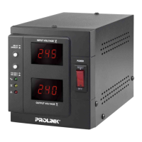
1. Power switch
2. Output voltage
display/Startup countdown
display (Only for Digital
display)
3. Input voltage display
4. Handle (Optional for
500VA/1000VA)
5. Startup delay time switch
6. Input voltage range
selector
7. Power LED (Green)
8. AVR LED (Yellow)
9. Over-voltage / under-
voltage indicator (Red)
10. Output sockets
11. AC input
12. Grounding (black)
13. Line output terminal
(brown)
14. Neutral output terminal
(black)