EasyManua.ls Logo

Promac 212 - Electrical System; Wiring Diagram; Electrical Components List

Promac 212
17 pages
Print Icon
To Next Page IconTo Next Page
To Previous Page IconTo Previous Page
Loading...
Electrical system
ELECTRICAL SYSTEM
212 / 212Z
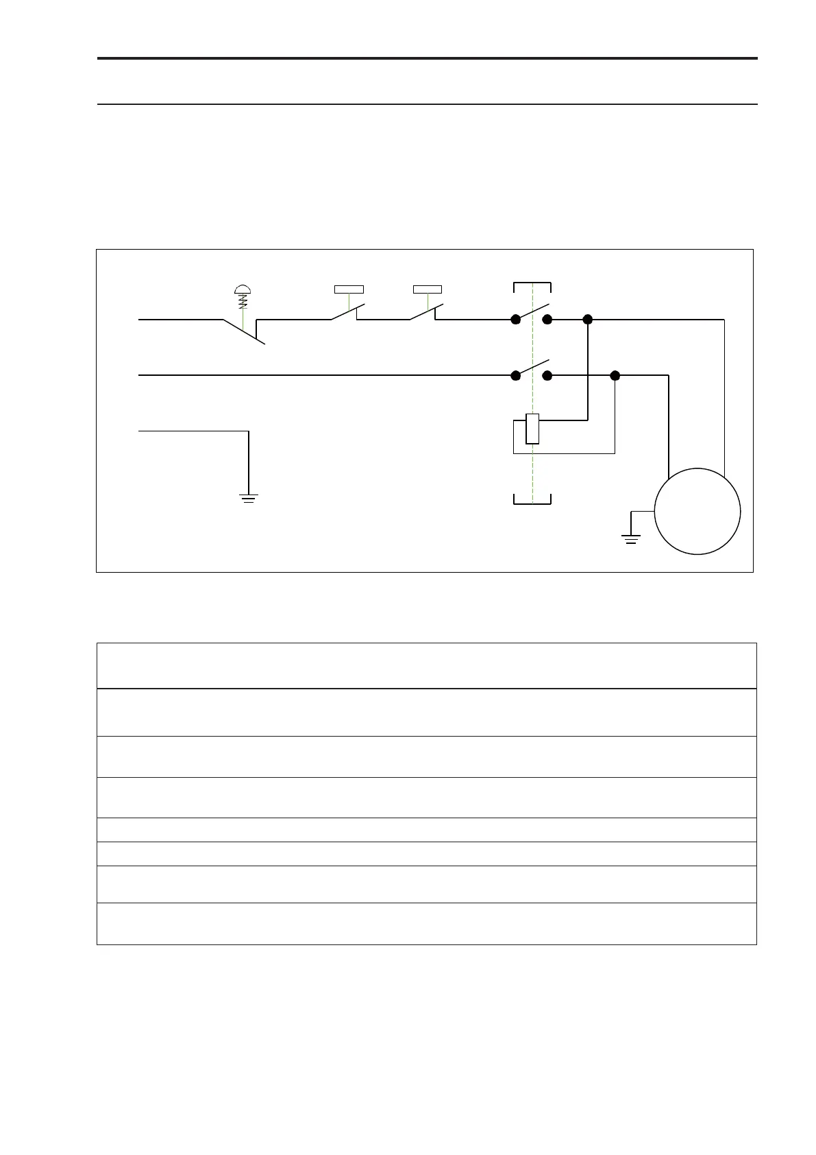
The wiring diagram, 230Volt, which can also be found in the motor cover, contains all necessary information
for the correct connection of your machine to the mains. If the mains connection (plug) has to be changed,
this task must be carried out by a qualified technician.
WIRING DIAGRAM
Electrical components Parts List
Symbol
Function
Technical Data
Parts
Remarks
L1, L2
Power plug
Power cable
250V, 10-16A
H05VV-F 1.5mm2
1
K1 / SB1
“Start” Switch
AC 230V / 10A
1
KEDU, KJD-12
K1 / SB2
“Stop” Switch
AC 230V / 10A
1
KEDU, KJD-12
M
Motor
DC 230V / 0.37Kw
1
PE
Electrical grounding
SB3
Microswitch Cover /
AC 230V / 6A
1
SHINOZAKI, AZD-S11
Emergency switch
EN 60947-5-1
SB4
Chip guard switch
AC 230V / 6A
1
Model 212Z only (France)
7
MOTOR
AC 230 8A
K1
PE
4
K1
3
230V/50HZ/1PH
L2
2
1
L1
SB1 SB2
SB5
SB4
SB3