Do you have a question about the ProMariner TruePower Combi and is the answer not in the manual?
Details the two-year limited factory warranty against defects in material and workmanship.
Provides contact information and address for factory service and technical support.
Covers FCC Class A compliance and potential interference issues in residential areas.
Warns of high voltage risks and the need to turn off AC power before work.
Warns about explosive fumes and making connections in flammable atmospheres.
Warns of electrical burns and sparks from low voltage.
Advises caution for hot surfaces and proper battery selection.
Emphasizes saving and reading the manual's instructions for TruePower Combi models.
Lists AC pass-through specifications for different TruePower Combi models.
Details DC input amperage for various TruePower Combi models.
Warns about explosive hydrogen gas from lead-acid batteries during operation.
Guidance on calculating total electrical loads for application based on ABYC E-11.
Instructions for applying use factor percentages for fixed electrical loads.
Covers safety advice for working with batteries: acid contact, sparks, and battery types.
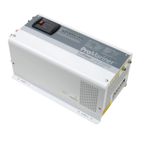
Instructions for unpacking and inspecting the TruePower Combi unit for damage.
Explains the unit's smart technology, alarms, and indicators for monitoring.
Describes the unit's function as a Pure Sine or Quasi Sine wave inverter.
Details the unit's function as a high-efficiency automatic battery charger.
Describes the internal automatic 30 amp AC transfer switch.
Provides the formula from ABYC E-11 for calculating required kVA.
Offers a worksheet to calculate maximum total leg amps per ABYC E-11.
Outlines LED and buzzer indicators for fault and status modes.
Details LED indicators on the remote panel for status and faults.
Explains the function of the Auto Standby/Off/On switch for the inverter.
Describes the switch settings for selecting different battery types for charging.
Lists LED colors and their corresponding functions for charger and inverter modes.
Explains the connection for the optional remote status panel and operating switch.
Details DC connection points, including corrosion resistance and safety notes.
Lists recommended maintenance tasks and their frequency (start-up, monthly).
Describes the procedure for resetting the unit by turning it off and on.
Verifies proper connections and settings before initial startup.
Steps for starting the charger feature after installation.
Steps for starting the inverter and transfer switch features.
Explains the function and operation of the unit's cooling fan.
Details the essential DC grounding conductor and its compliance.
Describes the audible warnings accompanying fault modes.
Explains protection for the charger feature against overloads.
Explains protection for the inverter feature against overloads.
Details the connections for AC output from the inverter.
Details the connections for AC input to the charger feature.
Specifies materials for DC cable overcurrent protection (fuses/breakers).
Covers protection and strain relief for AC and DC terminals.
Outlines requirements for the main panelboard, including voltmeter.
Details DC cable sizing, termination, and recommended tools.
Provides proper cable size recommendations for AC connections.
Discusses battery types, isolation, and setting the unit accordingly.
Specifies the operating voltage range for the TruePower Combi.
Explains the 3-stage charging process (bulk, absorption, float).
Describes the equalization feature for lead-acid batteries.
A checklist to follow before using the Combi charger/inverter.
Lists LED indicators for the charger mode and their functions.
Details remote panel LED configurations for charger mode.
Provides sequential steps for starting the unit in inverter mode.
Specifies minimum recommended battery bank and connection types.
Details AC input connection markings and descriptions.
Details AC output connection markings and descriptions.
Details DC input/output connection markings and descriptions.
Lists LED indicators for the inverter mode and their functions.
Details remote panel LED configurations for inverter mode.
Steps to energize AC circuits connected to the inverter.
Discusses safety features and typical appliance load ratings.
Lists applications and their wattage requirements for inverter mode.
Discusses DC power consumption and battery life in inverter mode.
Illustrates installing the unit to power a single dedicated AC device.
Illustrates installing the unit to power an entire AC panelboard.
Explains high initial wattage requirements for motor appliances.
Advises staggering appliance startups to avoid overloading.
Recommends recharging batteries before full discharge for longevity.
Details suitable location requirements, avoiding heat and flammable areas.
Guidance on placing the remote status panel and cable routing.
Emphasizes ensuring adequate space for servicing and maintenance.
Advises on routing DC cables and choosing a location near the battery bank.
Prohibits mounting the unit directly above or below batteries.
Details secure mounting methods for the heavy unit.
Illustrates installing the unit with a split-bus AC wiring configuration.
Explains the split bus option for energizing only certain circuits.
Steps for removing and repositioning the remote panel.
Instructions for disconnecting the short pigtail from the unit.
Steps to install the provided dummy panel after remote panel removal.
Guidance on finding a suitable mounting location for the remote panel.
Illustrates powering the entire AC panelboard with the unit.
Discusses how load and time affect battery usage.
Diagram illustrating the split-bus system installation.
Explains inrush current and limits for appliance operation.
Advises on managing multiple appliance startups.
Recommends monitoring battery status for optimal lifespan.
Stresses the necessity of the earth connection for safe operation.
Discusses battery bank configuration (series vs. parallel).
Lists applications and their wattage requirements for inverter mode.
Discusses DC power consumption and battery life in inverter mode.
Details AC input connection markings and descriptions.
Details AC output connection markings and descriptions.
Details DC input/output connection markings and descriptions.
Lists LED indicators for the inverter mode and their functions.
Details remote panel LED configurations for inverter mode.
Steps to energize AC circuits connected to the inverter.
Discusses safety features and typical appliance load ratings.
Lists LED indicators for the charger mode and their functions.
Details remote panel LED configurations for charger mode.
Steps for starting the unit in inverter mode.
Details DC cable sizing, termination, and recommended tools.
Provides proper cable size recommendations for AC connections.
Discusses battery types, isolation, and setting the unit accordingly.
Explains the 3-stage charging process (bulk, absorption, float).
A checklist to follow before using the Combi charger/inverter.
Explains protection for the charger feature against overloads.
Explains protection for the inverter feature against overloads.
Details the connections for AC output from the inverter.
Details the connections for AC input to the charger feature.
Specifies materials for DC cable overcurrent protection (fuses/breakers).
Covers protection and strain relief for AC and DC terminals.
Outlines requirements for the main panelboard, including voltmeter.
Verifies proper connections and settings before initial startup.
Steps for starting the charger feature after installation.
Steps for starting the inverter and transfer switch features.
Lists recommended maintenance tasks and their frequency.
Outlines LED and buzzer indicators for fault and status modes.
Describes the procedure for resetting the unit by turning it off and on.
Details LED indicators on the remote panel for status and faults.
Explains the function of the Auto Standby/Off/On switch for the inverter.
Describes the switch settings for selecting different battery types for charging.
Lists LED colors and their corresponding functions for charger and inverter modes.
Explains the connection for the optional remote status panel and operating switch.
Details DC connection points, including corrosion resistance and safety notes.
Provides the formula from ABYC E-11 for calculating required kVA.
Offers a worksheet to calculate maximum total leg amps per ABYC E-11.
Instructions for applying use factor percentages for fixed loads.
Covers safety advice for working with batteries, including acid contact, sparks, and battery types.
Covers FCC Class A compliance and potential interference issues.
Warns of high voltage risks and the need to turn off AC power.
Warns about explosive fumes and making connections in flammable atmospheres.
Warns of electrical burns and sparks from low voltage.
Advises caution for hot surfaces and proper battery selection.
Emphasizes saving and reading the manual's instructions.
Lists AC pass-through specifications for different models.
Details DC input amperage for various models.
| Output Power | 1000W |
|---|---|
| Battery Voltage | 12V |
| Battery Type | AGM, Gel |
| Inverter Power | 1000W |
| Charging Stages | 3-Stage (Bulk, Absorption, Float) |
| Battery Compatibility | AGM, Gel |
| Protection Features | Short Circuit, Reverse Polarity |
| Cooling | Fan Cooled |