12VDC for P2
or P3 only
Torque Switches (if equipped)
For units equipped with torque switches:
Torque switches provide mechanical
overload protection for both the actuated
device and the geartrain.
These are factory set and are not
adjustable without proper equipment.
Torque switches are set to limit actuator
torque to approximately 105% of the
actuator rated output.
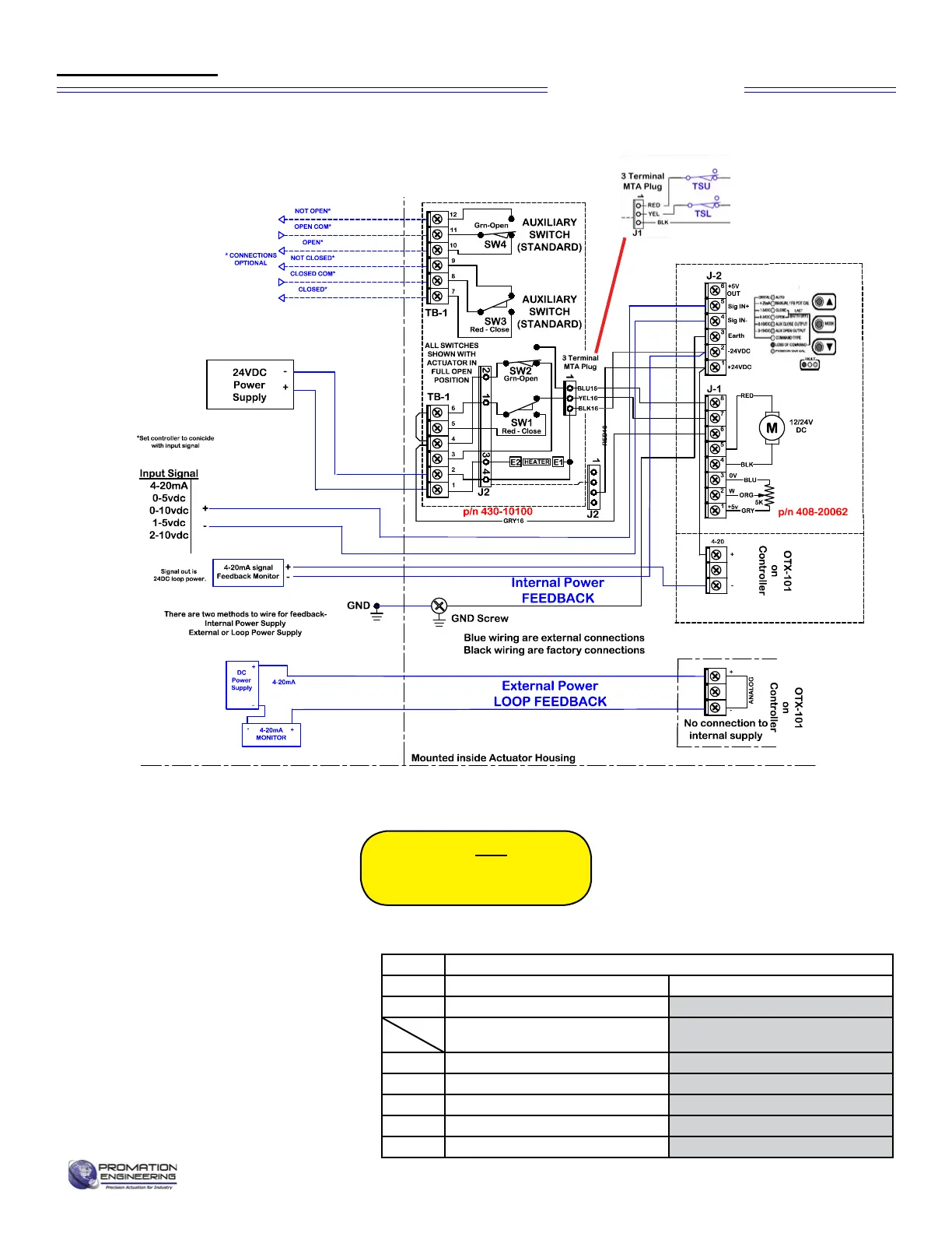
The wiring diagram above shows the
internal wiring connections between
the control board, the torque switches
and the motor. The upper torque switch
controls loading in the CW direction,
while the lower switch controls loading in
the CCW direction.
Wire sizing data is provided in the table to
assist in the selection of the proper wire size for
ProMation actuators using various wire sizes
over distance.
Please make sure to reference the correct
voltage and do not exceed the indicated length
of the wire run for each model.
WARNING! Do NOT adjust the
torque switch cam settings.
This will VOID the warranty.
Optional torque switch wiring (-TS) is interposed
between motor end of travel wiring and controler
Page 4 of 17 P2/3 12V 24DC Proportional Series
MAX distance between Actuator and Supply (feet)
Actuator
P2 P3
Voltage
24VAC/VDC 24VAC/VDC
4.5A 5.0A
16
58 52
14
93 84
12
143 128
10
242 218
8
362 326
Wire
Gage
Amps
Wire Sizing Chart
FM_P28 24 PN4-DC Ver E 080223
Wiring Diagram
Proportional Control