The Default Settings of the controller are as follows:
• Input Signal: 4-20mA (may be changed)
• Output Signal: 4-20mA (cannot be changed)
• Signal Response: Direct Acting (open = CCW)
• Loss of Command: Fail in Position
Input Signal Options:
• 4-20mA (default)
• 1-5vdc, 0-5vdc, 0-10vdc (Wire as shown on page 4, J2,
terminal 6 and select Command Type from Calibration Menu.
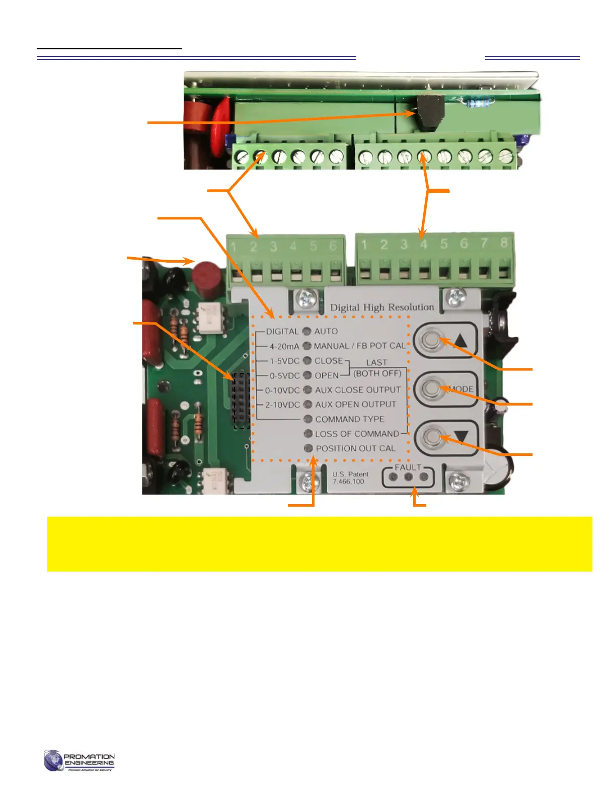
J2 Connector
J1 Connector
Calibration Menu
J3 Connector
for Optional
Feedback
or Modbus
Control
Options
For MODBUS
control paramters,
see
[ProMation Modbus
prmtrs 800-192B.
pdf]
MODE
Button
Select ▼
Button
Select ▲
Button
Fuse
Calibration LED Indicators
Fault Detection:
• Fault Indicator will flash and motor outputs are
turnedountilallfaultsarecorrected.
• All Faults show on the same LED
• See Fault Table for priority listing of faults
Controller Notes:
• Limit (Cam) Switches (SW1 and SW2) can cause
a Motor Stall Fault if set too close to the 0° (CW)
or 90° (CCW) positions.
This proportional control card has been calibrated and tested at the factory to operate
between 0 degrees and 90 degrees operating range. Controller position settings control the
actuator, adjustment of cam settings may aff ect controller operation, resulting in a fault.
Proportional Control
Fault LED Indicators
J7 Connector
The AC Controller Shown.
Calibration sequence is the
same for both AC and DC
Diagram of Controller
Page 5 of 17 P2/3 12 24 VDC Proportional Series
FM_P28 24 PN4-DC Ver E 080223