Proscend Communications Inc. All rights reserved. www.proscend.com
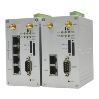
M350 Series Industrial Cellular Router
Quick Installation Guide
Version: 1.00
STEP 1: Before inserting or removing the SIM/SD card, ensure that the
power has been turned off, or the power connector has been
removed from the M350 Series Cellular Router.
STEP 2: Using a screwdriver to remove the metal protective cover first,
insert the SIM/SD card into the card slot. For SIM1 and SIM2, the
cut-off edge of SIM cards are to the right. For the SD card, the
cut-off edge of SD card is to the left.
STEP 3: Push the SIM/SD card and lightly press it to lock into the slot.
STEP 4: Remove the SIM/SD card, lightly press it and it will pop out the slot.
Insert and Remove SIM/SD Card
WPS and Reset functions are merged into one button.
Reset Button
Function
WPS Processing
Reset
Reset to default setting
Operation
Press the button less than 5 seconds.
Press the button for 5-10 seconds.
Press the button for more than 10 seconds.
There are four terminals on the terminal block with two terminals used for
each digital input and two terminals used for each digital output.
Pin
DI +
DI −
DO +
DO −
Description
Digital Output
Digital Input
Connecting I/O Ports
DI: Low (+0 to +3V) / High (+10 to +30V)
DO: Photo relay (maximum 50V/500mA)
Four LAN ports and one WAN port are used for 8-pin RJ45 connectors.
Each Ethernet port has two LED indicators.
LED Indicators of Ethernet Port
RS-232 interface on the right panel is the terminal block type.
COM (RS-232)
Pin
TX
RX
G
Signal
Transmit Data
Receive Data
Signal Ground
Direction
Output
Input
-
RS-485 supports 2-wire half duplex operation.
COM (RS-485)
Pin
D +
D −
G
Description
Serial Port, Data+ (A) wire
Serial Port, Data− (B) wire
Signal Ground
There are four models for the M350 Series, and each model has its own
antenna type to install on the assigned connector, as shown in the following
table.
▪ANT1, ANT2, and ANT5/GPS are on the right panel of the device.
Antenna Installation
DIP Switch
Two terminal blocks (PW1, PW2) are on the right panel.
The power input voltage is 8 ~ 48 VDC.
The other one is a DC Jack type on the front panel.
The power input voltage is 12 VDC, 2A.
Connecting the Power Supply
LED Indicators
LED
SYS
FN
SIM1
SIM2
RSSI1 L
RSSI1 H
WiFi
RSSI2 L
2.4GHz
RSSI2 H
5GHz
Off
Power down
User defined
Not working
Not working
N/A
N/A
Wi-Fi off or
unavailable
N/A
N/A
On
System up
User defined
Connected
Connected
Low signal
High signal
Wi-Fi on
RSSI2 L: Low signal
Wi-Fi 2.4GHz on
RSSI2 H: High signal
Wi-Fi 5GHz on
Slow
Booting
User defined
Connecting
Connecting
N/A
N/A
N/A
N/A
N/A
Fast
N/A
User defined
Error
Error
N/A
N/A
N/A
N/A
N/A
Heartbeat
N/A
User defined
Reading
Reading
N/A
N/A
N/A
N/A
N/A
The following table explains the LED indicators on the front panel.
1000M 10/100M
LED
1000M
10/100M
Blinking
Data Transmitting
Data Transmitting
On
1000Mbps LINK UP
10/100Mbps LINK UP
Off
LINK DOWN
LINK DOWN
DIP Switch
1
2
3
Mode
BS−
BS+
TRM
ON
Enabled (D−) 1K ohm Pull Low
Enabled (D+) 1K ohm Pull High
Enabled 120 ohm Termination
between (D+) and (D−)
OFF
Disabled (D−) Pull Low
Disabled (D+) Pull High
Disabled Termination
ON DIP
BS−
BS+
TRM
123
WPS/RESET
NOTE:
(D+), (D−) stands for RS-485 pinouts.
BS−, BS+ must be at the same ON/OFF position.
ANT1
5G
Antenna
5G
Antenna
LTE
Antenna
LTE
Antenna
ANT2
5G
Antenna
5G
Antenna
LTE
Antenna
LTE
Antenna
ANT3/WiFi
Wi-Fi
Antenna
Wi-Fi
Antenna
ANT4/WiFi
Wi-Fi
Antenna
Wi-Fi
Antenna
ANT5/GPS
5G
Antenna
5G
Antenna
GPS
Antenna
GPS
Antenna
ANT6
5G
Antenna
5G
Antenna
M350-5G
M350-W5G
M350-6
M350-W6
Connector
Model
- 1 -