Do you have a question about the Proteco LEADER 4 and is the answer not in the manual?
Manufacturer's declaration of product compliance with EU directives and standards.
Explains the LEADER operator range for residential swing gates and its intended purpose.
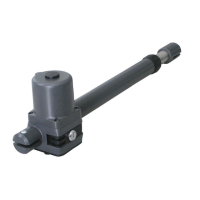
Lists the components included in the LEADER TI and LEADER TA kits.
Provides dimensional drawings and measurements for LEADER TI and LEADER TA models.
Essential checks to perform before installing the gearmotor to ensure suitability and safety.
Instructions for wiring the gearmotor, including standard installation and cable specifications.
Guidance on identifying and mounting the correct Left Hand (LH) or Right Hand (RH) handed motor.
Instructions on how to physically attach the gearmotor to the gate post and leaf.
Recommendations for vertical placement of the gearmotor based on gate sturdiness.
Guidance on horizontal positioning relative to the gate post, considering hinged leaf types.
Instructions specific to automating gates that open outwards, including dimension calculations.
Tables detailing bracket positioning for different LEADER models based on leaf length.
Instructions for welding or bolting the rear bracket T1 to the post, considering LH/RH orientation.
Steps for attaching the front bracket S3 to the gate leaf for LEADER TI models.
Specific instructions for fastening the front bracket S3 on LEADER TI models.
Specific instructions for fastening the front bracket S4 on LEADER TA models.
| Power Supply | 230V AC |
|---|---|
| Motor Voltage | 230V AC |
| Motor Type | Asynchronous |
| Motor Power | 300W |
| Max Gate Weight | 400 kg |
| Operating Temperature | -20°C to +55°C |
| Protection Level/Rating | IP44 |
| Safety Features | Obstacle detection |