NOTE:
For reference purposes, all instructions are given looking at the com-
ponent side of the module with the Green LED at the top. Refer to
the wiring diagram for detailed terminal designations.
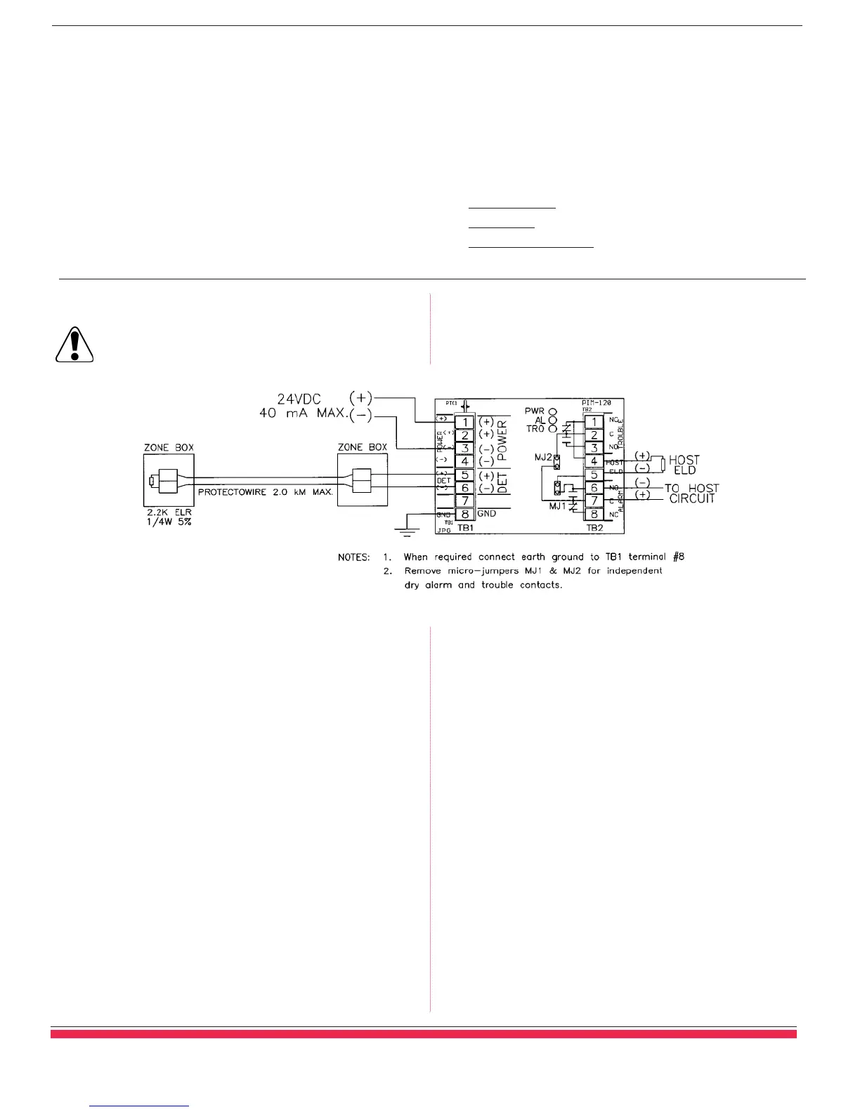
5. Connect a regulated 24 VDC switched power source across
input terminals 1 & 3 marked POWER (+) & (-) on TB1. Turn
on power. Only the green “POWER ON” LED should be on
and the host panel initiating device circuit trouble indication
should clear. When grounding is required by code or local
authority, connect terminal 8 marked GND on TB1 to earth
ground.
6. At the end of the Protectowire Linear Heat Detection loop open
the circuit at the 2.2K end-of-line resistor. The yellow
“TROUBLE” LED on the PIM-120 Interface Module will light
and the host panel should report a trouble condition. Reconnect
the end-of-line resistor and the “TROUBLE” LED will extin-
guish and the host panel should reset to normal. Note: Manual
trouble reset of the host panel may also be required depending
upon the make and model installed.
7. At the end of the Protectowire Linear Heat Detection loop, short
the circuit at the 2.2K end-of-line resistor. The red “ALARM”
LED on the PIM-120 will light and the host panel should report
an alarm condition. To restore the system to normal, reset the
host control panel. The interface module’s Protectowire alarm
initiating circuit is non-latching and self-restores upon clearing
the initiating circuit alarm state.
Specifications
Electrical
• Regulated 24 VDC (+10% / -15%) @ 20 mA standby,
40 mA alarm.
• Power limited, onboard surge and EMI protection devices.
•
Individual Alarm (red), Trouble (yellow) and Power On
(green) LED’s.
• Initiating Device Circuit: Max. 2,000 m (6,560 ft.) of
Protectowire Linear Heat Detector or any number of normally
open non-resistive contact devices. Not compatible with 2-wire
smoke detectors.
DS 9206A-0807 (2C)
© 2006 The Protectowire Company, Inc.
PIM-120 Commissioning Procedure
Caution: All auxiliary alarm devices and outputs controlled
by the Host Fire Alarm Panel should be disconnected prior to
connecting the PIM-120 Zone Interface Module to the system.
1. Install a 2.2K ohm 1/4w 5% end-of-line resistor (ELR) across
the conductors at the end of the Protectowire run.
2. Measure Protectowire Linear Heat Detector loop resistance prior
to connection. Total loop resistance should be between 2.2K and
3.7K ohms. Connect Protectowire Linear Heat Detector across
terminals 5 & 6 marked DET (+) and (-) on terminal block TB1.
3. Connect host panel’s end-of-line device across terminals 4 & 5
marked HOST ELD on terminal block TB2. See host panel
wiring specification, if polarity is required, connect (+) to
terminal 4, (-) to terminal 5.
4. Connect host panel’s initiating device circuit across terminals
6 & 7 marked ALARM C & NO on TB2. See host panel wiring
specification, if polarity is required, connect (+) to terminal 7, (-)
to terminal 6. The host panel’s initiating device circuit must
accept normally open alarm shorting and normally closed trouble
opening devices.
Environmental
•
Ambient temperature: 0 - 49˚C (32˚ - 120˚F)
• Humidity: Max. 95% non-condensing.
Outputs
• One set of Form C (SPDT) Alarm Contacts and one set of
Form C (SPDT) Trouble Contacts rated 1 amp @30 VDC.
Ordering Information
Model Number:
PIM-120
Description: Single Zone Mini-Interface Module; track mounted.
Mounting Dimensions: 7.6(w) x 5.0(h) x 2.5(d) cm
[3(w) x 2(h) x 1(d) inches]
The Protectowire Company, Inc.
■
40 Grissom Road, Plymouth, MA 02360-7205 U.S.A.
■
p:781-826-3878
■
f:781-826-2045
web: www.protectowire.com
■
email: pwire@protectowire.com
SPECIAL HAZARD FIRE DETECTION SYSTEMS
 Loading...