Do you have a question about the Protectowire CTM-530 Series and is the answer not in the manual?
Explains the principles behind CTI digital linear heat detection technology.
Describes the basic operation of digital linear heat detectors.
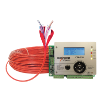
Provides an overview of the CTM-530 as an interface for linear heat detectors.
Describes the CTM-530's operation, features, and indicators.
Details electrical power, environmental operating ranges, and humidity limits.
Lists the LED indicators and LCD display details for status monitoring.
Describes the Form C relay contacts and 4-20mA output functions.
Outlines the module's physical dimensions and available enclosure types.
Details the mA output levels for various module status conditions.
Explains the 4-20mA output for alarm point location and calculation formulas.
Provides guidance on selecting an appropriate mounting location for the module.
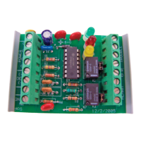
Illustrates the field wiring diagram and essential connection points.
Details how to connect the Protectowire Linear Heat Detector to the module.
Covers termination requirements and interface connections to the host panel.
Explains the requirements and connections for the module's power supply.
Details the wiring procedure for the 4-20mA output loops.
Outlines requirements before configuring and testing the detection equipment.
Describes the LCD display, navigation controls, and menu access.
Details password entry, error handling, and detector reset procedures.
Details how to select the appropriate detector type for proper operation.
Allows selection between US Standard and Metric units for measurements.
Explains the calibration process for the Alarm Point Location feature.
Procedure to set the real-time clock and date for the module.
Details how to change user and technician level passwords.
Describes how to reset all module settings to factory defaults.
Explains how to access and view the module's 64-event history buffer.
Details cold junction compensation measurement and offset adjustment.
Details the procedure for calibrating the 4-20mA output loops for accuracy.
Notes on testing procedures and inspection of the installation.
Procedure to verify correct polarity of detector connections.
Procedure to test the module's detection of an open circuit condition.
Procedure to test the module's detection of a short circuit condition.
Continues the procedure for testing short circuit detection.
Tests the alarm activation function using a simulated heat source.
Continues testing alarm activation and temperature readings.
Procedure to verify the accuracy of temperature measurements using a test meter.
Lists and describes various probe types and temperature meters for testing.
Continues listing and describing probe and meter types for testing.
Details the purpose and operation of the intrinsic safety barrier.
Explains RS-485 and Modbus protocol fundamentals.
Describes how the CTM-530 integrates with Modbus over RS-485 networks.
Details RS-485 port compatibility and Modbus protocol information.
Shows the wiring diagram for the RS-485 port and an example bus configuration.
Guides on setting slave address, parity, and baud rate for Modbus communication.
Explains how to access the Modbus configuration menu.
Procedure to set the unique slave address for each module.
Details how to configure the parity setting for Modbus communication.
Explains how to configure the baud rate for the Modbus network.
Provides a general overview of the Modbus protocol.
Introduces the concept of internal registers for Modbus data.
Details the meaning of status bits in the module's holding register.
Describes Modbus registers for temperature readings.
Describes Modbus registers for event distance measurements.
Describes the Modbus register for cold junction temperature.
Explains the Modbus register for configuring the detector type.
Details the Modbus register for re-initializing or resetting the module.
| Model | CTM-530 Series |
|---|---|
| Type | Control Unit |
| Input Voltage | 24 VDC |
| Number of Zones | 1 |
| Alarm Output | Form C relay, 2 A @ 30 VDC |
| Humidity | 0-93% Non-condensing |