Page 26
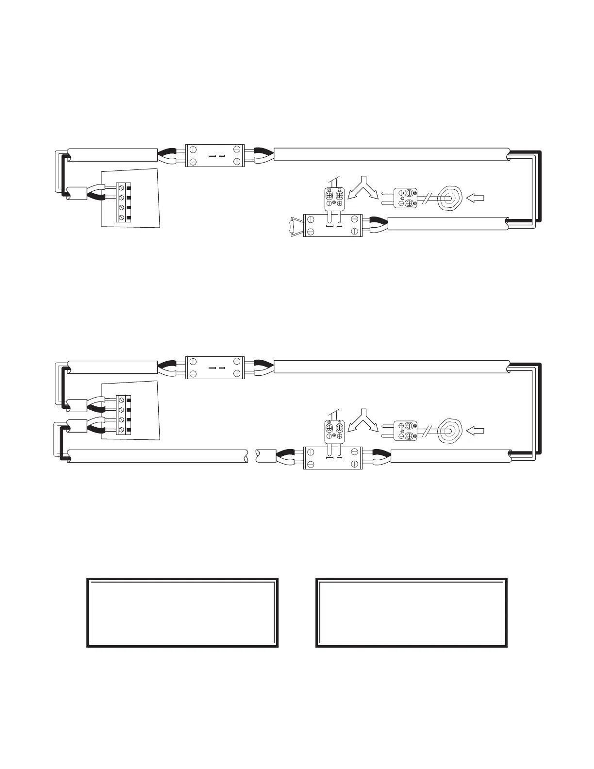
Step 3 - Testing Alarm Activation with Confi rmed Temperature Initiation (CTI) - To test the alarm
activation function of the CTM-530 a thermocouple junction must be created at the end of the linear heat
detector. It is NOT recommended that the detector be heated as a means of testing since the activation
portion of the detector would be destroyed in the test and would then need to be replaced. Instead a probe
is connected at the end of the linear heat detector to simulate an alarm event. For a Class B circuit insert a
calibrated “T” type thermocouple probe into the test jack as show in fi gure 17.
DRTB Terminal
With Test Jack
+
+
-
+
-
CU CO
-
T
CTM-530
FIELD TERMINALS
(+)
(-)
(+)
(-)
J11
OUT
RET
Extension Cable
Silver Conductor (-)
End Line
Resistor
10K 1/2W
Copper
Conductor (+)
LINEAR HEAT DETECTOR
LINEAR HEAT DETECTOR
Class B Wiring
LINEAR HEAT DETECTOR
TC - EXT
DRTB Terminal
With Test Jack
+
+
-
+
-
CU CO
-
T
Type “T” Thermocouple Probe
Apply Heat
Source
HEAT
Figure - 17
For a Class A circuit insert a “T” type thermocouple probe into the test jack of the return input terminals as
shown in Figure 18. Note that with the probe installed the Class A loop is still connected to both the Outgo-
ing and Return terminals. This ensures the temperature measurement will be read in both directions.
DRTB Terminal
With Test Jack
+
+
-
+
-
CU CO
-
T
CTM-530
FIELD TERMINALS
(+)
(-)
(+)
(-)
J11
OUT
RET
Extension Cable
Extension Cable
Silver Conductor (-)
Copper Conductor (+)
Silver Conductor (-)
Copper Conductor (+)
LINEAR HEAT DETECTOR
Class A Wiring
LINEAR HEAT DETECTOR
LINEAR HEAT DETECTOR
TC - EXT
TC - EXTENSION CABLE
DRTB Terminal
With Test Jack
+
+
-
+
-
CU CO
-
T
Type “T” Thermocouple Probe
Apply Heat
Source
HEAT
Figure - 18
The thermocouple probe will cause a short circuit in the detection loop and the CTM-530 will fi rst indicate
a short circuit fault. Confi rm the temperature of the short fault is properly measured at the CTM-530 being
sure both the Out and Return readings are displayed for Class A circuits.
Protectowire CTI-190
SHORT FAULT
DIST: 456 FT
TEMP: 78°F
Protectowire CTI-190
SHORT FAULT - RETURN
DIST: 27 FT
TEMP: 79°F
Short Fault Display Short Fault Return Display
* Class A Only
 Loading...