Page 22
Operation and Testing
Testing Notes - The CTM-530 must be confi gured and tested before service. Confi guration and testing of
detection equipment shall be performed by competent, qualifi ed personnel having jurisdiction over this de-
tection equipment. Any monitoring equipment connected to the CTM-530 should be bypassed or disabled
during testing to avoid unintended activation of the monitoring equipment. Remote monitoring sould then
be verifi ed under controlled conditions as the fi nal phase of testing.
It is recommended all linear heat detection installations be tested and inspected for proper operation a mini-
mum of once per year.
Inspection of the Installation - Before performing any operational testing of the detection system it is rec-
ommended that the following inspections be performed:
Visually inspect the linear heat detector installation and confi rm conformance with the Installation, Op-
eration and Maintenance Manual for Protectowire Linear Heat Detectors. Check for any signs of physical
damage or wear to the detector and associated installation hardware.
Confi rm that the Installation and Setup Confi guration of the CTM-530 conforms to the applicable installa-
tion and confi guration sections of this manual.
During the inspection process make note of the location and quantity of all fi eld connections including zone
boxes, end of line boxes and fi eld splices. All terminations should be inspecgted for proper conneciton and
polarity. Confi rm all connections are suitable for the environment in which they are located, i.e. properly
sealed or contained within a properly rated enclosure.
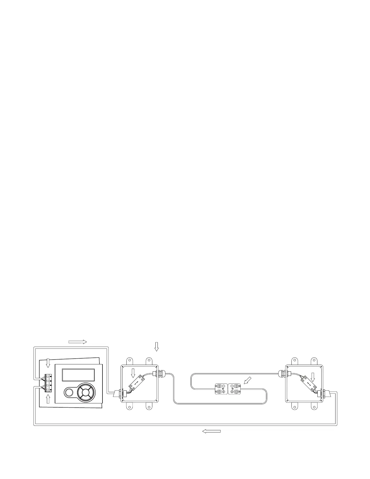
Confi rming Detector Connection Polarity - The polarity of ALL CTI Linear Heat Detector connection
must be observed. Verify the polarity of all connections during testing using the following procedure.
With the CTM-530 module powered and in a NORMAL standby condition, measure the voltage across
terminal J11 In (+) and (-), verify a reading of (+) 1 VDC. Confi rm that the conductor connected to the (+)
terminal is a copper colored conductor and the conductor connected to the (-) terminal is a silver colored
conductor. Measure the voltage at each connection point in the loop confi rming the polarity of the reading
and confi rm all (+) connections are made with copper colored conductors and terminals and all negative (-)
connections are made with silver colored conductors and terminals. Correct any incorrect polarity or termi-
nations before moving to the next point.
Mini-Thermocouple Connector
with Pre-Installed Short Jumper
OUT ZONE BOX
WITH TEST JACK
Protectowire CTI
TM
Linear Heat Detector
= Indicates connections where polarity must be tested
Extension Wiring
CTM-530
OUT
OK
ESC
Protectowire CTI-155
NORMAL
10:58AM 8/19/2013
1
2
3
4
J11
RETURN ZONE BOX
WITH TEST JACK
+
+
-
+
-
CU CO
-
T
RETURN
Field Splice
See Splice Instructions
+
+
-
+
-
CU CO
-
T
Figure - 11
 Loading...