Page 8
Installation and Wiring - (continued)
Wire the system according to this manual using Figure 6 as reference. Wiring should be in accordance with
applicable National and/or Local Electrical Fire Alarm Codes.
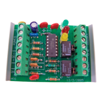
Detector Wiring - The CTM-530 provides one (1) supervised detection circuit that may be fi eld wired for
either Class A (Style D) or Class B (Style B)service. The alarm initiating circuit is capable of operating up to
4000 feet (1220 meters) of Protectowire Type CTI Linear Heat Detector. The CTM-530 initiation circuit is
designed to monitor Protectowire Type CTI Linear Heat Detector only and does not support other types of
normally open contact alarm initiating devices.
Step 1 - Remove the factory supplied 10K 1/2w end-of-line resistor (ELR) from terminal J11 TC1
(+) and (-). Retain this resistor for installation at the end of the detector run as shown in the Class
“B” fi eld wiring diagram (Figure 6). For Class “A” confi guration the ELR shall be
removed and discarded.
Step 2 - Connect the Protectowire Linear Heat Detector to the CTM-530 interface module at
terminal J11 as shown in the fi eld wiring diagram (Figure 6) in either a Class “B” or Class “A”
confi guration
Important!: Polarity MUST be observed in all wiring confi guration. Copper colored conductor is Positive
and Silver colored conductor is negative. For all CTI type detectors, twisted “T” type extension grade ther-
mocouple wire is required for use as interconnecting wire on the detection circuit. Minimum conductor size
is 20AWG (0.812mm), or as required by local code. See operation and testing section for polarity verifi ca-
tion procedure.
Wiring Terminations - All termination and or splices in the CTI detector loop must be mad utilizing ter-
minals rated for “T” type thermocouple connections. Use of standard terminals will impair operation of the
detector. Only zone boxes and splicing connectors specifi cally recommended by The Protectowire Co., Inc.
shall be utilized.
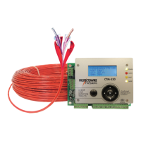
Interface Wiring - The CTM-530 is a detection control module that is an interface between a main fi re alarm
control panel detection circuit or addressable node and Protectowire Type CTI Linear Heat Detector. The
most common interface connections utilize the trhee from “C” contacts provided for Fault, Short Fault and
Alarm conditions.
Step 3 - Connect the hosts panel’s initiation device circuit(s) to terminals J13 as shown on the fi eld
wiring diagram (Figure 6). Reference the host panel wiring specifi cations for correct wiring
confi guration and requirements. Connection Diagram #1 depicts a short being monitored as a
“Fault” condition by the host. Connection Diagram #2 depicts a short being monitored as either a
separate pre-alarm or supervisory condition by the host panel.
 Loading...