Page 10
Confi guration and Feature Selection
Confi guration Prerequisites - The CTM-530 must be confi gured and tested before service. Confi guration
and testing of detection equipment shall be performed by competent, qualifi ed personnel having jurisdiction
over this detection equipment. Monitoring equipment connected to the CTM-530 should be bypassed or
disabled prior to setup to avoid unintended activation of the monitoring equipment.
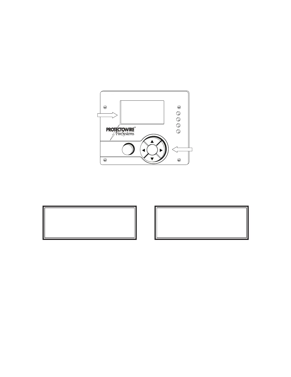
Display, Menus and Navigation Controls - The standard version of the CTM-530 has an integrated LCD
display an navigation controls which allow user access to the detectors status information and the setup
menu.
K1
K2
K3
LINEAR
HEAT
DETECTOR
POWER
ALARM
FAULT
SHORT
OKESC
PROTECTOWIRE CTI-155
NORMAL
12:45 PM 4/16/2020
LCD Status
Display Screen
Navigation
Switches
Initial Power Up - When power is applied, the CTM will go through a short boot sequence. The green
power on LED will illuminate and the boot screen will display the currently confi gured detector type fol-
lowed by the fi rmware version and date. When the boot sequence is complete the module will display a
normal status message.
Protectowire CTI-155
V1.3.5 4/24/2020
Protectowire CTI-155
NORMAL
9:45AM 4/24/2020
Boot Screen Status Screen
Accessing the Menu - The CTM-530 menu is password protected. The two levels of access are User lev-
el (USER) and Technician (TECH) level. User level access is limited to Detector Reset and Event History
viewing functions. Technician level access permits full access to the confi guration menu.
To enter the Menu press the center navigation button labeled “OK” and the password entry screen will
appear.
Note: During menu access detection monitoring is halted. While detection monitoring is halted the CTM-
530 will report a fault condition via the “FAULT” led indicator and the fault contacts will transfer. Normal
standby operation will be restored once the menu is exited and detection monitoring resumes.
 Loading...