The Proteus 800 Series Metering Flow Switches are designed for monitoring and controlling liquid flow rates from 0.05 to 50 GPM (0.2 to 190 LPM) across extended temperature and pressure ranges. These devices are developed from Proteus' extensive experience in flow sensing applications since 1978.
Function Description:
The 800 Series flow switches operate by measuring the rotation of a rotor as liquid flows through the meter. Magnets embedded in the rotor interact with a Hall-effect sensor mounted in the meter body, generating a pulse train. This pulse train is then converted by the electronics into a voltage proportional to the linear velocity of the liquid. This voltage output serves two primary functions: switching and metering.
For switching, the measured output voltage is continuously compared to a user-selected trip point voltage. If the measured voltage is above the trip point, the built-in relay remains in its active state. If the voltage falls below the trip point due to reduced or stopped flow, the relay contacts open, signaling an alarm condition to the control system.
For metering, the 800 Series provides a calibrated 0-5VDC output, with 5VDC corresponding to the maximum flow rate of each version. This allows for the determination of the actual flow rate in a circuit by attaching a voltmeter. An optional scaleable digital voltmeter can be calibrated to provide a direct local display of the flow rate.
Important Technical Specifications:
- Flow Ranges: Available in eight flow ranges from 0.05 to 50 GPM (0.2 to 190 LPM).
- Materials: Available in brass, polypropylene, or stainless steel.
- Connections: NPT and SAE connections are available.
- Operating Temperature:
- -40 to 100°C (-40 to 212°F) with standard polysulfone faceplate.
- -40 to 140°C (-40 to 284°F) with stainless steel or brass faceplates.
- Electronics must be thermally isolated from the flow sensor at temperatures above 85°C and below the dew point.
- Operating Pressure: Up to 250 psi (1720 kPa).
- Kinematic Viscosity: Up to 120 centistokes.
- Wetted Materials:
- Flow Sensor Body: 304 Stainless Steel
- Faceplate: 316 Stainless Steel
- Sealing O-ring: Viton® (other materials available)
- Rotor: Carbon fiber-filled Nylon
- Rotor Shaft: 316 Stainless Steel (other materials available)
- Voltage Output: 0–5 VDC for the maximum rated flow for each sensor type.
- Accuracy: ± 2% of full scale. Improved accuracy and linearity can be achieved with specialized NIST-traceable calibration.
- Linearity: Better than ± 1% from 10 to 100% of nominal full scale.
- Reproducibility: Better than ± 0.5% above 10% of nominal full scale.
- Trip Point Selection: 16-position switch changes trip points in steps of 6% of nominal full scale, with fine adjustment between steps via an optional potentiometer.
- Hysteresis / Dead Band: < 5% of actual flow rate.
- Switch Type: Relay Closure, SPDT 48 VDC, 1.0 A.
- Power Requirements: 24 VDC, 40 mA.
- Electrical Connection: Plug type EDZ1550/8 with screw fastening for 8 conductors up to #16 gauge.
- Certifications: CE marked for compliance with EU Directive 89/336/EEC (Electromagnetic Compatibility), Safety Certified by RWTUV as a low voltage, Class III device.
Usage Features:
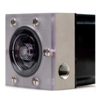
- Compact Design: The 800 Series units are designed to be compact, with the side view volume reduced by up to 50% compared to previous models. This makes them easily retrofittable, as mechanical and electrical interfaces are identical to hundreds of thousands of Proteus 24VDC flow switches and flow meters already in use.
- User-Selectable Trip Point: Trip points are adjusted using a 16-position switch, providing predictable, accurate, and reproducible settings without complex instrumentation. An optional potentiometer allows for finer tuning of the trip point.
- Instant Status Information (LED): A tri-color LED (green, amber, red) provides immediate visual indication of flow status, similar to a traffic signal.
- Green: Actual flow > 1.15 x flow rate at selected trip point (Relay: Closed NO, Open NC).
- Amber: Between 1x and 1.15 x flow rate at selected trip point (Relay: Closed NO, Open NC).
- Red: Actual flow < flow rate at selected trip point (Relay: Open NO, Closed NC).
- The LED being ON confirms 24VDC power and functional flow switch.
- Multiple Outputs: Electrical interfacing is via an 8-pin connector, offering various control options and delivering 24VDC power. This includes connections for power input, ground, output voltage, normally closed relay contact, common relay contact, normally open relay contact, and remote LED anodes.
- Flow Direction Insensitivity: The 800 Series Metering Flow Switch is not sensitive to flow direction, allowing liquid to be introduced from either side.
- Digital Displays: Optional panel-mounted digital display meters are available to provide a direct local display of flow rate in GPM or LPM on a 3½ digit LCD display with 0.6-inch high digits and a DIP switch-selectable decimal point.
Maintenance Features:
- Cleaning: Maintenance primarily involves cleaning the rotor chamber and annual recalibration. The frequency of cleaning depends on the liquid type and cleanliness.
- Procedure: Turn off liquid flow, remove the sensor, remove the 6 screws securing the faceplate, remove the faceplate, rotor, and stainless steel shaft. Remove the O-ring. Clean all components with a soft cloth dampened with alcohol, water, or a dilute detergent solution.
- Inspection: Inspect the rotor and stainless steel shaft for wear or damage. Replace if worn or not round. Inspect the O-ring for brittleness or cracks, replacing if necessary with a #132 O-ring.
- Reassembly: Position the O-ring, place the rotor, align the faceplate, replace and tighten the 6 securing screws to 40 in-lbs.
- Recalibration: Calibration should be checked at 12-month intervals. Recalibration can be done by Proteus or another laboratory.
- Proteus Calibration: Involves measuring output, replacing rotor, shaft, and O-ring, cleaning the flow cavity, recalibrating to original specifications against NIST-traceable standards, issuing a new calibration certificate, and attaching a new calibration label.
- Fluid and Temperature Effects: Changes in fluid type or large changes in liquid temperature can alter the calibrated response of the sensor. Specialized calibration may be needed for specific fluids or connections with internal diameters smaller than those used in standard calibration.
- Filtering: While not essential for operation, filtering the circulating fluid with a 100-micron filter is recommended to remove rust and other particles, increasing the lifetime of pumps, fluid system components, and reducing wear in the sensor.