6
• LED provides instant status information.
Like a traffic signal, the green, amber and red lights indicate flow status so that problems are easily
detected. Green, amber and red lights provide instant indication of the status the flow switch and the
flow rate. An additional LED monitor can be remotely mounted at your control panel.
❖ If the three-color LED is ON you know that 24VDC power is being delivered to the flow
switch and the flow switch is functional.
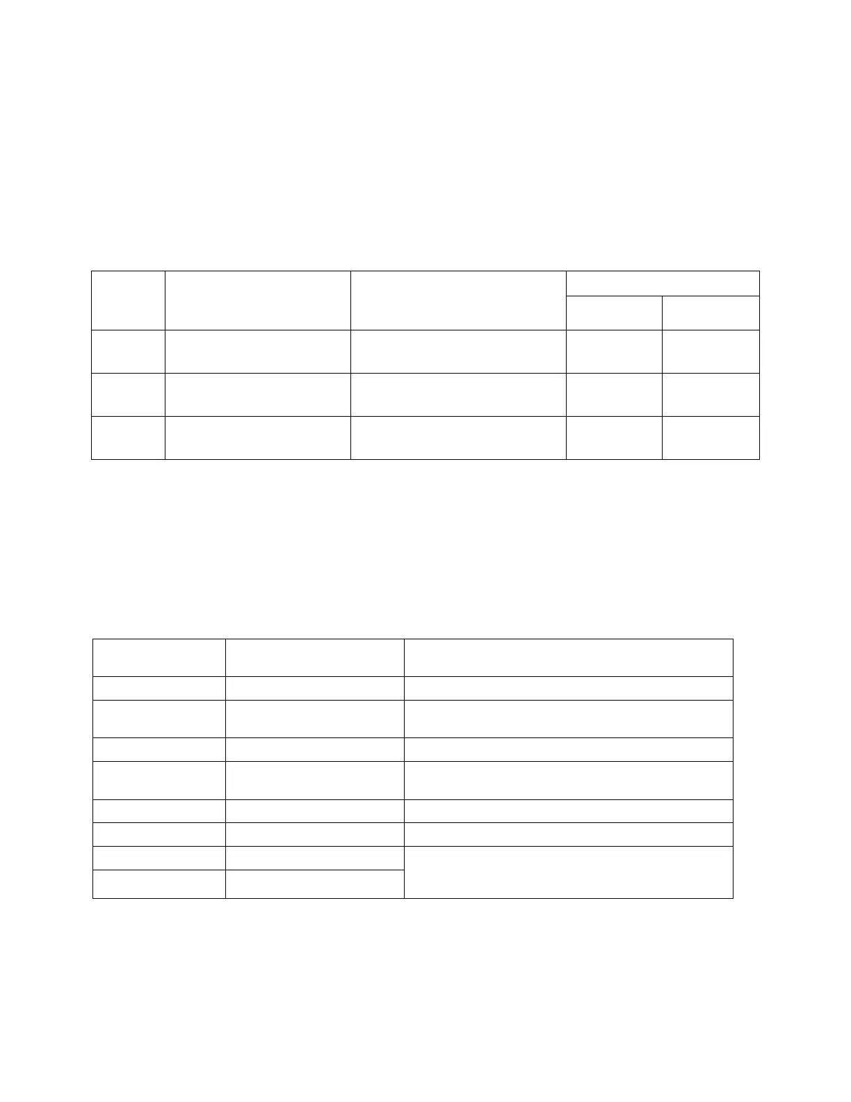
❖ The color of the LED changes depending on the ratio of the actual flow rate to the Trip Point
Example Trip Point 10 GPM
Greater than 1.15 x flow
rate at selected trip point
Between 1x and 1.15 x flow
rate at selected trip point
10 < Actual Flow < 11.5 GPM
Less than flow rate at
selected trip point
• Multiple outputs provide control flexibility
Electrical interfacing of the 800 Series units is effected through an 8-pin connector that provides a
range of control options while delivering 24VDC power. See Section 6, Installation for connection
details.
Ground connection for power
& output signals
Should be connected to a valid system ground
Calibrated to provide 5 VDC at the maximum flow rate
Normally Closed relay
contact
Connects to NC contact of relay.
Connects to Common contact of relay
Normally Open relay contact
Connects to NO contact of relay
Connections for a remote tri-color LED indicator.
Common cathode of tri-color LED should be connected
to ground