- 4 -
Technical Notebook ..............................................................
Technical Training
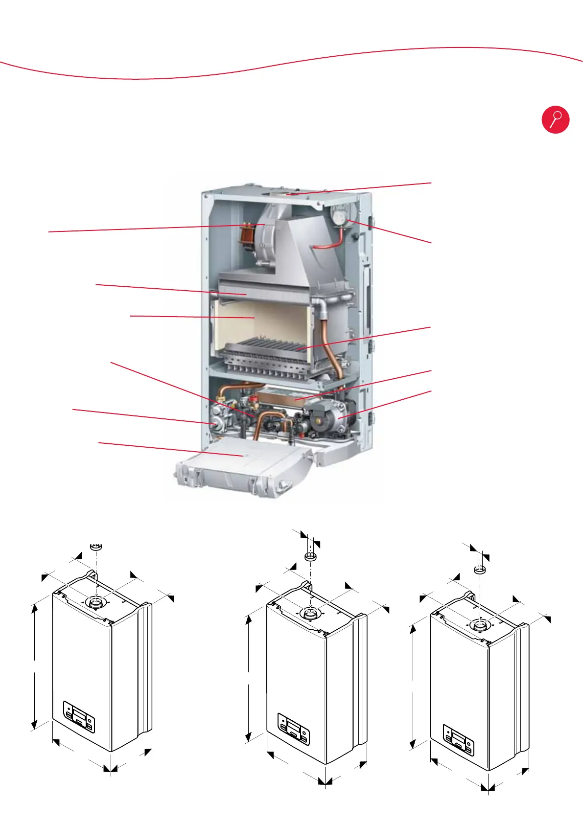
General presentation of the fan flue appliances
The structure of fan flue versions
Fan
Heat exchanger
Combustion chamber
Hydraulic bloc
Gas valve
Electrical box
Smoke outlet
Air ow switch
Burner
Plate heat exchanger
Pump
This picture is for Panther.
The Gepard is quite different on the
top part : the air ow switch is on
left side.
360
450
Ø46
807
230
225
311
410
742
179
205
Ø125
311
410
Ø41
742
184
205
311
410
742
158
175
(Ø43)
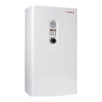
Panther 12 KTO
360
450
Ø46
807
230
225
311
410
742
179
205
Ø125
311
410
742
184
205
360
450
807
230
225
311
410
742
179
205
Ø125
311
410
Ø41
742
184
205
311
410
Ø36
742
158
175
(Ø43)
Panther 30 KTV
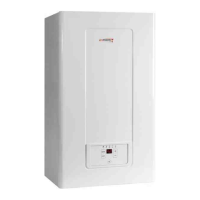
Panther 25 KTV,
25 KTO




 To Next Page