J-MAX™ ANTENNA MOUNT
ASSEMBLY INSTRUCTIONS
Contents:
A
B
C D E F G
Install Base to Mounting Surface
Install Pivot Bolt Through Top Hole in Base and Pole
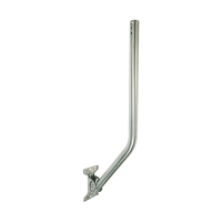
A. Base
B. Pole
C. M6 Pivot Bolt
D. M6 Long Lock Bolt
E. M6 Short Adjustment Bolt (x2)
F. M6 Serrated Flange Nut (x4)
G. M8 Lag Screw (x4)
Tools required: M10 & M13 Wrenches
Use the provided lag screws or other
fasteners appropriate for the surface
material.
Pole can be installed in either orientation.
Align the square portion of bolts with the
holes and insert fully.
Do not tighten pivot bolt nut until final pole
position is determined.
© Copyright, Proxicast LLC. All rights reserved.
Contents may vary depending on model - Specifications subject to change without notice.
www.proxicast.com
1
2
3
Rev 20211129