-9-
1pc. Allen key (for changing saw blade)
1pc. Allen key (for table adjustment)
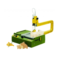
Description of the machine
We have developed ajig saw for especially high
requirements concerning sawing precision and
performance that is not only distinguished by its
versatility but is also suitable for cutting curves in
12 mm thick wood.
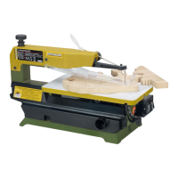
Straight cuts are no problem either: the machine
is equipped with an adjustable limit stop which is
guided along the tool edge, enabling accurate
parallel cuts. And because the saw table can also
be rotated alongthe longitudinal axle, mitre cuts
up to 45° are also possible.
The device head consists of precisely machined
die-cast zinc. It contains areduction gear for the
drive of the saw blade. The jig saw is powered by
an especially high quality and quiet direct current
motor.The speed can be preselected via elec-
tronic control: the correct of number of strokes is
then always set
Technical data
Dimensions, weight:
Length: 230 mm
Weight: 530 g
Motor:
Voltage: 230 volts, 50/60 Hz
Power consumption: 80 Watt, KB 5
Rational speed: 2000 -4500 min
-1
Vibration: <2,5 m/s
2
Noise emission: LPA87dB(A)
LWA100 dB(A)
General measuring
uncertainty: K=3 dB
Please note that the sound and vibration meas-
urements in particular have been performed with
PROXXON bits and cutters. When using third-
party brands we cannot guarantee compliance
with the statements given here!
Clamping and changing saw blades
Danger!
Injury hazard
Disconnect the mains plug before changing tools.
Note:
•Donot work with damaged or worn bits and cut-
ters! Make sure the sanding discs are in perfect
condition!
•When storing the bits and cutters, make sure
they are reliably protected from damage!
1. Loosen clamp screw using the Allen key 1pro-
vided (Fig. 2).
2. Insert saw blade (2) into slot in the saw blade
mount and re-tighten clamp screw.
Important
The saw blade must be located in the groove of
the support roller.
Setting the mitre angle
Danger!
Injury hazard
Disconnect the mains plug before proceeding.
1. Loosen clamp screw using the Allen key 1
(Fig. 3).
2. Adjust the saw plate (2) to the desired mitre
angle and re-tighten the clamp screw.
Setting the parallel stop
Danger!
Injury hazard
Disconnect the mains plug before changing tools.
1. Loosen clamp screw 1(Fig. 4) using the Allen
key provided
2. Adjust the stop (2) to the desired dimension
and re-tighten the clamp screw.
Note:
The stop can also be used for curved cuts. For
this purpose, position anail at the centre point of
the curve and use as axis for the stop. The scale
for curved cuts is on the back of the stop.