9. Attach the other end of the 6 inch length of 1/4 inch hose to the barb on the output side of the check valve; secure with a
clamp. (Flow is marked on side of check valve with an arrow.)
10. Mount the PZ2 ozone generator vertically on wall with compressor at lower end, using two holes in rain shield. Place
system at or above water level. If unit must be mounted below water level, loop the hose so that at some point it is above
water level (a solenoid control valve may be necessary). (See item 1 above, Preparing for Installation.)
11. Attach the remaining length of 1/4 inch hose between check valve and ozone generator; secure with clamps.
12. Electrical Installation: System is 120 or 240 VAC, 50/60 HZ. Wire Prozone ozone generator system to circulation pump
switch or timer. Prozone system and circulation pump should be activated simultaneously. Use N.E.C. or local code
grounding and installation procedures for swimming pool equipment.
CAUTION:
Make sure the voltage is the same as prescribed on the side of the Prozone ozone generator. Overvoltage will void
customer warranty.
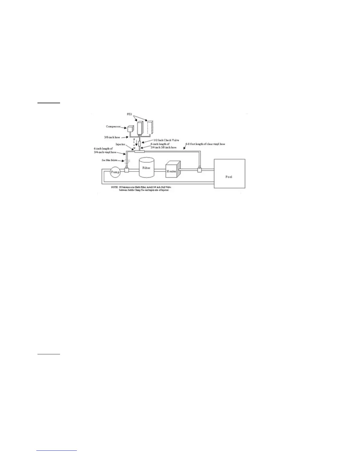
PZ2-4, PZ2-6, AND PZ2-8 SERIES WITH BYPASS VENTURI
1. Directly after pump and before filter, attach a 3/4 inch x 1 inch hose barb fitting to the plumbing using other appropriate
fittings (not provided).
2. After all existing equipment (including heater, chlorinator, etc.), attach another 3/4 inch x 1 inch hose barb fitting using
appropriate fittings (not provided).
3. Cut a 6 inch (15cm) length (plus or minus 1 inch) of 1 inch clear vinyl hose and connect to the barb on the 3/4 inch x 1 inch
fitting installed nearest to pump; secure with a clamp.
4. Insert venturi injector into the other end of the 6 inch length of 1 inch hose making sure flow is away from the saddle, and
secure with a clamp. Flow is marked on side of injector with an arrow.
5. Insert opposite end of injector into remaining length of 1 inch hose and secure with a clamp.
6. Attach loose end of 1 inch hose to second 3/4 inch x 1 inch fitting installed in step 2.
7. Apply Teflon tape to the threads of the two 1/2 inch x 3/8 inch fittings.
8. Screw these two ½ inch x 3/8 inch fittings into each end of the check valve.
9. Cut a 6 inch length of 3/8 inch braided hose and connect the check valve and venturi together; secure with clamps.
10. Mount the PZ2 ozone generator(s) vertically on wall using two holes in rain shield. Place system at or above water level. If
unit must be mounted below water level, loop the hose so that at some point it is above water level (a solenoid control
valve may be necessary).
11. Mount the compressor next to the ozone generator(s). (See item 1 above, Preparing for Installation.)
12. Cut a length of 3/8 inch braided hose long enough to reach between ozone generator and compressor.
13. Attach this length of hose to the ozone generator(s) and compressor; secure with clamps.
14. Attach one end of remaining 3/8 inch braided hose to the barb on the ozone generator and other end to the barb on the
input side of the check valve. Making sure flow is away from ozone generator, secure ends with clamps.
15. Electrical Installation: System is 120 or 240 VAC, 50/60 HZ. Prozone system and circulation pump should be started
simultaneously. Use N.E.C. or local code grounding and installation procedures for swimming pool equipment.
CAUTION:
Make sure the voltage is the same as prescribed on the side of the Prozone ozone generator. Overvoltage will void
customer warranty.
 Loading...