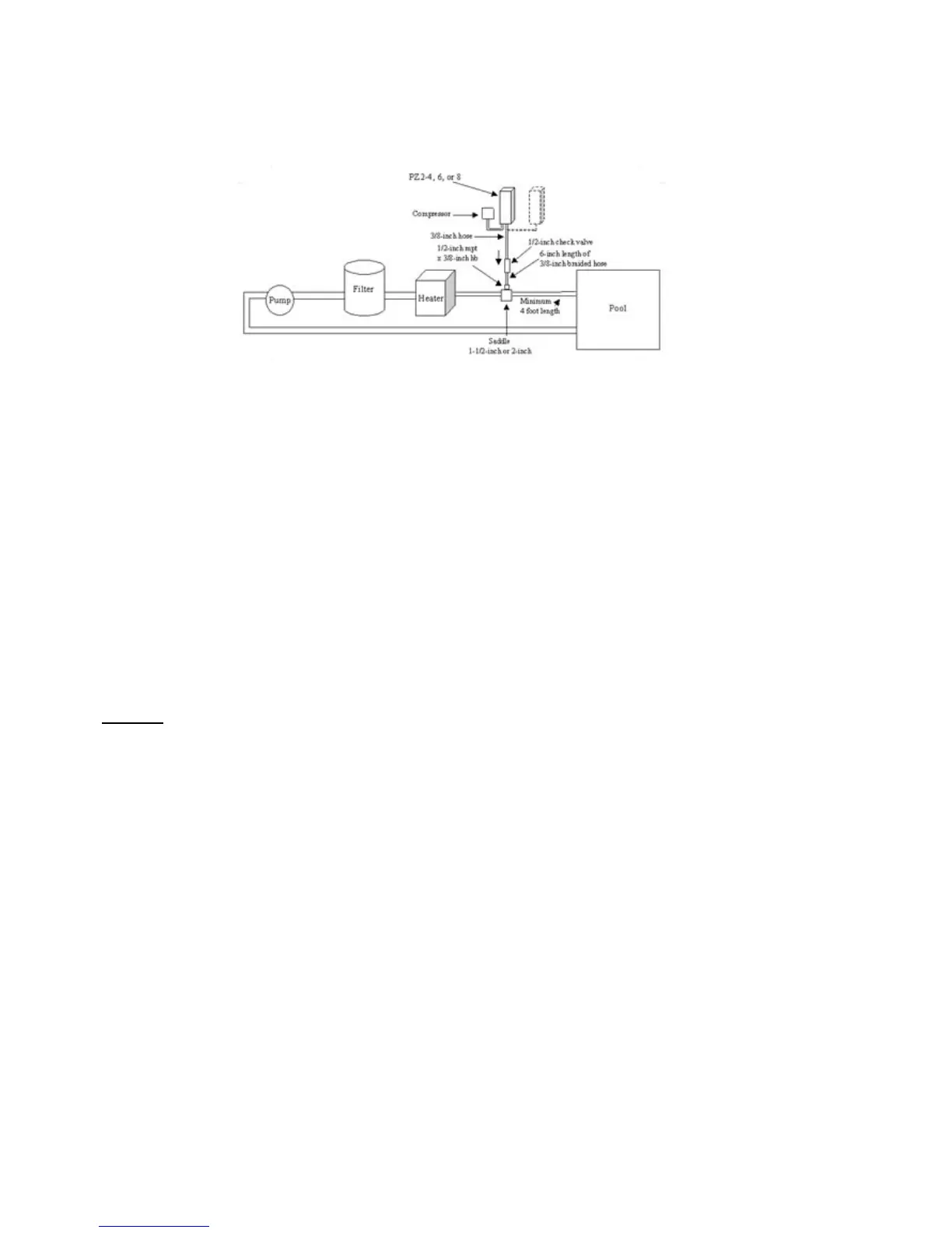
PZ2-4, PZ2-6, PZ2-8 WITH DIRECT INJECTION
NOTE: There must be at least four feet (1.2m) of return line between the point where the ozone bubbles are injected and the pool. If
there is not four feet of return available, a flexible loop can be added to the return line.
1. Apply Teflon tape to the threads of one of the 1/2 inch x 3/8 inch fittings and attach the fitting to the return line after the
heater and other equipment using other appropriate fittings (not provided).
2. Cut a 6 inch (15cm) length (plus or minus 1 inch) of 3/8 inch polybraid hose and slide it over the barb on this fitting. Secure
hose with a clamp.
3. Apply Teflon tape to the threads of the other two ½ inch x 3/8 inch fittings.
4. Screw these two ½ inch x 3/8 inch fittings into each end of the check valve.
5. Attach the other end of the 6 inch length of 3/8 inch hose to the barb on the output side of the check valve; secure with a
clamp. (Flow is marked on side of check valve with an arrow.)
6. Mount the PZ2 ozone generator(s) vertically on wall. Place system at or above water level. If unit must be mounted below
water level, loop 3/8 inch hose so that at some point it is above water level (a solenoid control valve may be necessary).
7. Mount the compressor next to the ozone generator. (See item 1 above, Preparing for Installation.)
8. Cut a length of 3/8 inch hose long enough to connect the ozone generator and compressor together; secure with clamps.
9. Attach the remaining length of 3/8 inch hose between input side of check valve (flow away from ozone generator) and
ozone generator; secure with clamps.
10. Electrical Installation: System is 120 or 240 VAC, 50/60 HZ. Wire Prozone ozone generator system to circulation pump
switch or timer. Prozone system and circulation pump should be started simultaneously. Use N.E.C. or local code
grounding and installation procedures for swimming pool equipment.
CAUTION:
Make sure the voltage is the same as prescribed on the side of the Prozone ozone generator. Overvoltage will void
customer warranty.
OPERATION
A. PROZONE PZ2 SERIES OZONE GENERATOR OPERATION
The Prozone system works when air is drawn across a high-energy vacuum ultraviolet (VUV) lamp, converting some air to ozone.
The ozone is introduced into the water either by direct injection or through a bypass venturi system. For direct injection, the venturi
injector is inserted directly into the return line of the pool creating a suction (vacuum) that draws the ozone into the venturi as the
water returns to the pool. The bypass venturi system takes water directly after the circulation pump (highest pressure point),
bypasses part of the water flow past filters, heater, etc. through a venturi injector, through contact tubing and then returns the water
back to the pool return line. A check valve is employed to prevent water backup in the event of system failure. The system should
be run 6-8 hours per day for best effect. Run time may vary depending on usage.
B. WATER CHEMISTRY
Water chemistry must be maintained to assure proper performance of the Prozone ozonator system and existing pool or spa
equipment. The following levels are recommended:
• pH - 7.2 to 7.6. Ozone is pH neutral and will not cause the pH value of the water to fluctuate.
• Sanitizers - A chlorine level of .5 ppm to 1 ppm is recommended.
• Shock - Non-lithium-based material such as Calcium Hypochlorite or Sodium Hypochlorite, etc.
 Loading...