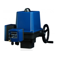
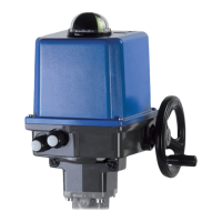
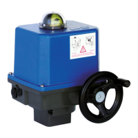
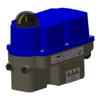
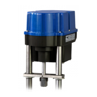
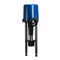
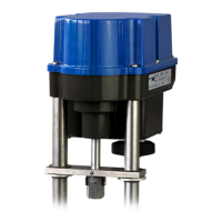
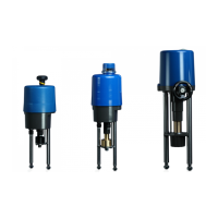
The PS-AMS PSQ quarter-turn actuators are designed for use as electric valve actuators, primarily for mounting on valves to control their motors. These actuators are built with state-of-the-art technology, ensuring safe operation when handled by sufficiently trained personnel and used according to specifications. Improper handling or use outside of specifications can lead to hazards, damage, and reduced safety.
Function Description
The actuators generate mechanical power using a 24-volt DC motor, controlled by electronics via pulse width modulation (PWM). Position feedback is provided by a precision potentiometer with absolute encoding. The motor torque is transmitted through a reducing spur gear to a planetary gear set, with the output being a center gear featuring a multi-toothed inner profile to accept the drive bushing.
In the event of power failure or during adjustment, the actuators can be emergency-operated via a handwheel, except when using the fail-safe unit PSCP. The handwheel drives the entire planetary gear set through a worm shaft. During motor operation, the handwheel remains stationary but is always available without needing to be clutched. Turning the handwheel clockwise also turns the output clockwise when viewed from the top.
The actuators are equipped with flanges conforming to ISO 5211 for valve mounting, and connection to the valve shaft is made with an exchangeable drive bush. For PSQ2003/2803AMS models, the flange is F16 with a 55 mm double square connection, and the actuator is delivered as two pre-mounted components: the gearbox and the actuator itself.
All internal parameters, such as required motor torque, actual position, and functional status, are continuously monitored during operation. This ensures optimal accuracy and tight valve closure. Deviations can be read out via communication software PSCS, local control PSC.2, or displayed through the fault indication relay, maximizing process safety.
Cut-offs can be adjusted using the PSCS software (via a special interface cable or optional Bluetooth connection) to optimize valve function. If a position is surpassed or not reached, this is indicated by the Fault Indication Relay or the PSCS software.
Three cut-off modes are available:
- Cut-off by Force / Torque: The actuator delivers the programmed maximum force/torque when driving to the end position. If the closing point within the valve shifts (e.g., due to seat gasket wear), the actuator will continue to drive within its possible actuation range to reach the programmed force/torque.
- Cut-Off by Position automatically: In normal operation, the actuator stops at the position found during Automatic Commissioning at a mechanical stop in the valve or actuator. If the closing point shifts, the actuator will not follow this dislocation but will always stop at the initially found point.
- Cut-Off by Position: In normal operation, the actuator stops at a position defined by Manual Commissioning, independent of any mechanical stop within the valve or actuator.
Important Technical Specifications
- Ambient Temperature: -20°C to +60°C.
- Operating Modes: S2 for short cycle and S4 for modulating operation (refer to actuator-specific data sheets for details).
- Lifetime: Meets Class C requirements according to DIN EN ISO 22153.
- Enclosure Rating: IP67 or IP68 according to EN 60529, for protection against moisture and dust.
- Motor: 24 volts DC, controlled by PWM.
- Position Feedback: Precision potentiometer with absolute encoding.
- Supply Voltage: Must comply with the actuator's nameplate.
- Input Terminals (Set-Value): Terminals 1-3 for parameterizable modulating set-value (0-20 mA or 0-10V).
- Input Terminals (Sensor Feedback - optional): Terminals 15-17 (main board) or 10-12 (terminal box) for process sensor feedback (0-20 mA or 0-10 V).
- Input Terminals (Binary Input): Terminals 9-11 (main board) or 17-19 (terminal box) for binary open/close signals (24 V to 230 V), driving the actuator in 3-point service.
- Input Terminals (Fail-safe port - optional): Terminals 12-13 (main board) or 25-26 (terminal box) for driving the actuator to a parameterizable safety position (24 V to 230 V).
- Output Terminals (Active Position Feedback): Adjustable within 0-20 mA or 0-10 V (main board: 4-6; terminal box: 4-6).
- Output Terminals (Additional Position Switches - optional): Potential-free changeover contacts (standard: 230 VAC/5 A silver contacts; low power: up to 100 mA and 30V gold-plated contacts available). Connection to X6/1-3 or X6/4-6 (limit switch board) or 22/27/28 or 23/29/30 (terminal box).
- Output Terminals (Voltage Feed to Process Sensor - optional): Terminals 14 and 17 provide an unregulated output voltage of 21-40 VDC at max 100 mA.
- Output Terminals (Fault Indication Relay): Potential-free relay contact (max load 24 VDC/100 mA) for adjustable fault indication to the control room (main board: 7-8; terminal box: 20-21).
Usage Features
- Installation Position: Can be mounted in any position except "cover facing downwards." Sufficient space must be left for cover removal.
- Wiring Arrangements: Available with wiring to the main board (requiring cover removal) or to a separate terminal box (requiring terminal box cover removal).
- Mechanical Mounting: Follow ISO 5211 flange standards. Ensure correct actuator and valve positions using the position indicator and handwheel. Tighten mounting screws diagonally.
- Commissioning:
- Automatic Commissioning: Initiated by pressing a commissioning button for about 3 seconds. The actuator will travel through its full adjusted range, and the green LED will flash quickly. Upon completion, the green LED glows permanently if no malfunction exists. Stop screws may need adjustment if end positions are not reached or are overridden.
- Manual Commissioning: Used when both cut-offs are "by position." Requires software PSCS or control box PSC. The actuator is driven to the closed position, and the open position is calculated based on the programmed valve stroke.
- Status Display: Red and green LEDs indicate actuator status. An optional red LED signals fieldbus interface status.
- Communication Port: RJ45 socket for communication cable to a PC, allowing parameterization via PSCS software.
- Safety Notes: Always isolate power supply before opening covers or working on electrical components. Ground the actuator. Avoid using the handwheel during ongoing motor operation if the actuator is trying to compensate for position deviation. Do not operate electrically during adjustment work; use the handwheel only. Beware of crushing fingers when the actuator is powered.
Maintenance Features
- General Maintenance: Under specified conditions, PS-AMS actuators are maintenance-free. All gears are lubricated for their service life and do not require re-lubrication.
- Cleaning: Clean actuators with a dry, soft cloth. Do not use cleaning agents, coarse, or abrasive materials.
- Troubleshooting: A detailed table of blinking codes for status LEDs is provided to trace faults, indicating probable reasons and possible remedies (e.g., check mains supply, repeat commissioning, check valve seat, contact PS service team).
- Accessories (Optional):
- Space Heater (HR): Prevents condensation build-up in environments with high temperature fluctuations or humidity. Powered via the actuator's power supply.
- Fieldbus Interface: For digital transmission of nominal/actual values, monitoring, and diagnostic data (Profibus DP, CANOpen).
- Integrated Process Controller: Enables autonomous process control without an external controller.
- Fail-Safe (PSCP): Emergency power supply based on supercapacitors for safety position.
- Local Control (PSC.2): Illuminated display, lockable selector for modes, control buttons, and diagnostic information.
- Remote Local Control: Separate mounting with a 10m connection cable.
- Data Cable (PSCS-USB): Enables communication between actuator and PC.
- Fail-Safe Port (FSP): Signal port to drive to a selectable safety position.
- Corrosion Protection (K2): Increased corrosion protection, including heating resistor.
- IP68 Enclosure: Increased enclosure rating.
- Terminal Box: Plug and socket in an IP68 box.
Decommissioning and Disposal
- Decommissioning: Disconnect mains supply, secure against accidental switching-on, open cover, remove electrical connections, and take off the actuator from the valve.
- Disposal: The product contains electrical and electronic equipment and must not be disposed of as household waste. It should be treated in accordance with 2012/19/EU (WEEE). Equipment can be returned to the manufacturer for proper disposal for a flat fee.