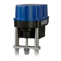
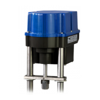
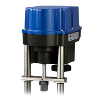
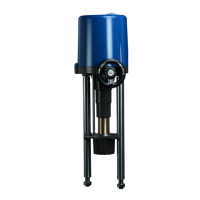
The PSF-Q electric actuators are designed for the operation of 90° quarter-turn actuators, primarily for mounting on valves to control their motors. These actuators are built with state-of-the-art technology and are considered safe to operate when handled by trained personnel and used according to specifications. Any other use is considered non-compliant, and the manufacturer disclaims liability for resulting damage. The actuators are designed to operate within the limits specified in data sheets, catalogues, and other documents.
Function Description
The PSF-Q actuators utilize a brushless DC motor (BLDC) to generate torque, which is transmitted via a multi-stage spur gear gearbox to a coupling with a double square drive, connecting to the valve shaft. The mechanical limitation of the rotation angle is continuously adjustable by ±5° in one end position. A linear 12-Bit Hall sensor measures and controls the rotation angle. In the event of mains power loss, the stroke movement defaults to either the OPEN or CLOSE direction via spring force. Electrical wiring is connected to a terminal block located under the actuator cover.
All internal parameters, including required motor torque, actual position, and functional status, are continuously monitored during operation to ensure optimal accuracy and tight valve closure. The actuator's approach to an end position depends on the selected switch position (S2-3/4/9). When "closing/opening with torque" is selected, a 3% end position retraction is active in both directions, rendering switch S2-1 non-functional. In "opening with swing angle" operating modes, the actuator remains in the open position set during automatic or manual calibration. The end position reached by torque always includes a 3% retraction.
The "Set value signal/Split range" switch position (S2-2/7/8) allows the set value to be split into a lower or upper range, enabling control of multiple actuators with a single set value signal. Switch position S2-10 can be used to select the relationship between the set value and the actuator position, offering two curves: a linear valve curve where actuator position in % corresponds to the set value in %, and a "Quick Opening Curve" for fast valve opening with a small set value.
Important Technical Specifications
- Actuator Type: PSF-Q 50 / PSF-Q 80
- Output Valve Shaft Direction: CW (clockwise) / CCW (counterclockwise)
- Voltage Supply: 24 VAC, 100-240 VAC (optional)
- Frequency: 50-60 Hz
- Max. Input Power: 22 W / 28 W
- Torque: 50 Nm / 80 Nm
- Operating Speed: 25 s / 30 s
- Enclosure Rating: IP65 (optionally IP67) according to EN 60529, providing protection against moisture and dust.
- Operating Modes: Correspond to IEC 60034-1, 8: S2 for short cycle, and S4 for control operation (actuator-specific values in data sheets).
- Ambient Temperatures: Standard actuators can be operated at ambient temperatures specified in the data sheet.
- Electrical Connections: Standard actuators have specific wiring diagrams provided inside the actuator. Separate wiring diagrams are available for optional accessories.
- Signal In- and Output: Connections for signal in- and output are double isolated from circuits that may be under dangerous voltage.
Usage Features
- Valve Mounting: The actuators feature a mechanical interface compliant with ISO 5211 for valve mounting, with an exchangeable drive bush to connect to the valve shaft. Ensure the actuator flange and plug-in coupling match the valve design. Lubricate the valve shaft slightly and tighten screws diagonally.
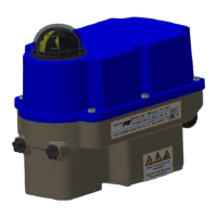
- Position Indicator: A two-coloured half ball turning under a transparent dome with blackened quarter segments indicates the position. It can be adjusted by removing the cover and turning the half ball.
- Electric Supply: Mains connecting cables must be dimensioned for the actuator's maximum current. Yellow-green cables are exclusively for earth connection. Observe the maximum bending radius when inserting cables through the drive cable connector. A switch or power mains switch must be provided in the building installation, positioned close to the device and easily accessible, labelled as the mains isolator switch. Power surge trips or fuses corresponding to IEC 60364-4-41 (protection class I or III for 24 VAC/VDC) are required. Power supply and control cables should be protected mechanically and run in separate lines.
- Manual Operation: An electrical manual override via push-buttons (B1 and B2) is available for commissioning and adjustment.
- To enter manual operation mode: Press B1 and B2 simultaneously for at least 3 seconds.
- To output valve shaft clockwise (CW): Press B1.
- To output valve shaft counterclockwise (CCW): Press B2.
- To exit manual operation mode: Press B1 and B2 simultaneously for at least 3 seconds.
- Automatic Commissioning:
- Ensure secure connection between valve and actuator.
- Start by pushing button B2 for at least 7 seconds.
- Option 1 ("open with torque – close with torque"): Actuator drives to final open valve position via torque, then back to final closed valve position.
- Option 2 ("open with travel"): Actuator stores open position with torque end stop and stops at the saved position during normal operation.
- Successful commissioning is indicated by the green LED flashing 7 times.
- Push B1 to return to normal operation.
- Verify the determined rotation angle by comparing set value and valve position.
- Unsuccessful commissioning is indicated by the green LED flashing quickly; check valve mounting.
- A residual rotation angle of at least 2° in end positions is necessary before the actuator reaches its mechanical stop.
- Manual Commissioning:
- Ensure secure connection between valve and actuator.
- Activate by pushing button B1 for at least 7 seconds.
- Use B1 and B2 for manual operation until the desired open valve position is reached.
- Store both positions by simultaneously pushing B1 and B2 for at least 3 seconds.
- Successful commissioning is indicated by the green LED flashing 7 times.
- Push B1 to return to normal operation.
- Verify the set rotation angle by specifying the setpoint and measuring the actual value.
- Unsuccessful commissioning is indicated by the green LED flashing quickly.
- A residual rotation angle of at least 2° in end positions is necessary before the actuator reaches its mechanical stop.
- Status Display (LEDs):
- Actuator not commissioned: Green Off, Red flashing quickly.
- Normal operation / Actuator running: Green On, Red Off.
- Normal operation / Actuator stationary: Green Off, Red On.
- Manual mode active: Green flashing alternately, Red flashing alternately.
- Manual mode: output valve shaft counterclockwise (CCW): Green Off, Red flashing.
- Manual mode: output valve shaft clockwise (CW): Green flashing, Red Off.
- Automatic commissioning running: Green On, Red On.
- Automatic and manual commissioning successful: Green flashing 7x – 1.5 seconds off, Red On.
- Automatic commissioning failed: Green flashing quickly, Red On.
- Overvoltage: Green flashing 1x – 1.5 seconds off, Red On.
- Undervoltage: Green flashing 2x – 1.5 seconds off, Red On.
- Memory error: Green flashing 3x – 1.5 seconds off, Red On.
- Set value error (< 1 V, < 2 mA): Green flashing 4x – 1.5 seconds off, Red On.
- Torque error: Green flashing 5x – 1.5 seconds off, Red On.
- Under- / overtemperature: Green flashing 6x – 1.5 seconds off, Red On.
- Blue LED: Indicates "Ready for operation" when supply voltage is applied, and helps read DIP switches.
Maintenance Features
- General Maintenance: Actuators are maintenance-free when used under specified operating conditions. Gearboxes are lubricated for life and do not require further lubrication.
- Cleaning: Actuators should be cleaned dryly. Avoid abrasive cleaning agents or solvents, as they can damage safety stickers and type plates. Do not operate the actuator during cleaning.
- Cover Removal/Closing:
- Opening: Loosen and unscrew hexagon socket screws from the gear casing. Carefully remove the cover to avoid damaging the injected seal.
- Closing: Place the cover on the gear casing, press down slightly, then tighten screws gently and crosswise.
- Safety: Open the cover only in a dry environment. Ground the actuator and touch grounded housing parts before opening.
- Spring-Pretensioned Design: The actuators contain a pre-tensioned spring. The gearbox housing must not be opened. Defective actuators should be returned to the plant in Bad Duerkheim, Germany, or to representatives for damage inspection.
- Outdoor Usage: For environments with high temperature fluctuations or humidity, a heating resistor is suggested to prevent condensation build-up within the enclosure.
- Decommissioning and Disposal:
- Disconnect and secure the mains supply against accidental switching-on.
- Open the cover and remove external electrical connections.
- Remove the actuator from the valve.
- For disposal, the product should be treated as waste containing electrical and electronic equipment and not disposed of as household waste.
- Due to the pre-tensioned spring, contact the plant in Bad Duerkheim for disassembly.
Accessories
Various options are available to adapt actuators to different service conditions, including:
- Position Signal Relays (2 position signal relays with changeover contacts): Automatically calibrated to angular travel, 24 V to 230 V AC/DC @ 0.1 A-1A, with switching points adjustable 0-100% of the stroke using potentiometers.
- Heating Resistor (HR): To prevent condensation.
- Wide Range Power Supply: 100-240 VAC 1~.
- Increased Enclosure (IP): To increase enclosure rating to IP67.