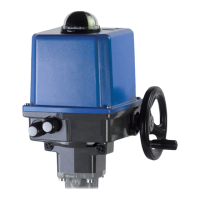
9. Adjustment of the position indicator
10. Electric supply
10.1 Safety instructions
Before connecting to the mains, ensure that the mains supply is isolated and secured against an
accidental switching-on.
Remove the cover of the actuator in order to connect the electric supply (see 8.).
The mains connecting cables must be suitably dimensioned to accept the max. current requirement of the actuator.
The yellow-green coloured cables may only be used for connecting to earth.
When you insert the cable through the drive cable connector, ensure that the max. bending radius for the cable is
observed.
PSF-Q electric actuators do not have an internal electrical power switch. A switch or power mains switch must be
provided in the building installation. It should be positioned closely to the device and be easily accessible for the user
and shall be labelled as the mains isolator switch for the actuator.
The building installation must also provide power surge trips or fuses corresponding to standard IEC 60364-4-41 with
protection class I resp. protection class III (24 VAC / 24 VDC) for the actuator connections.
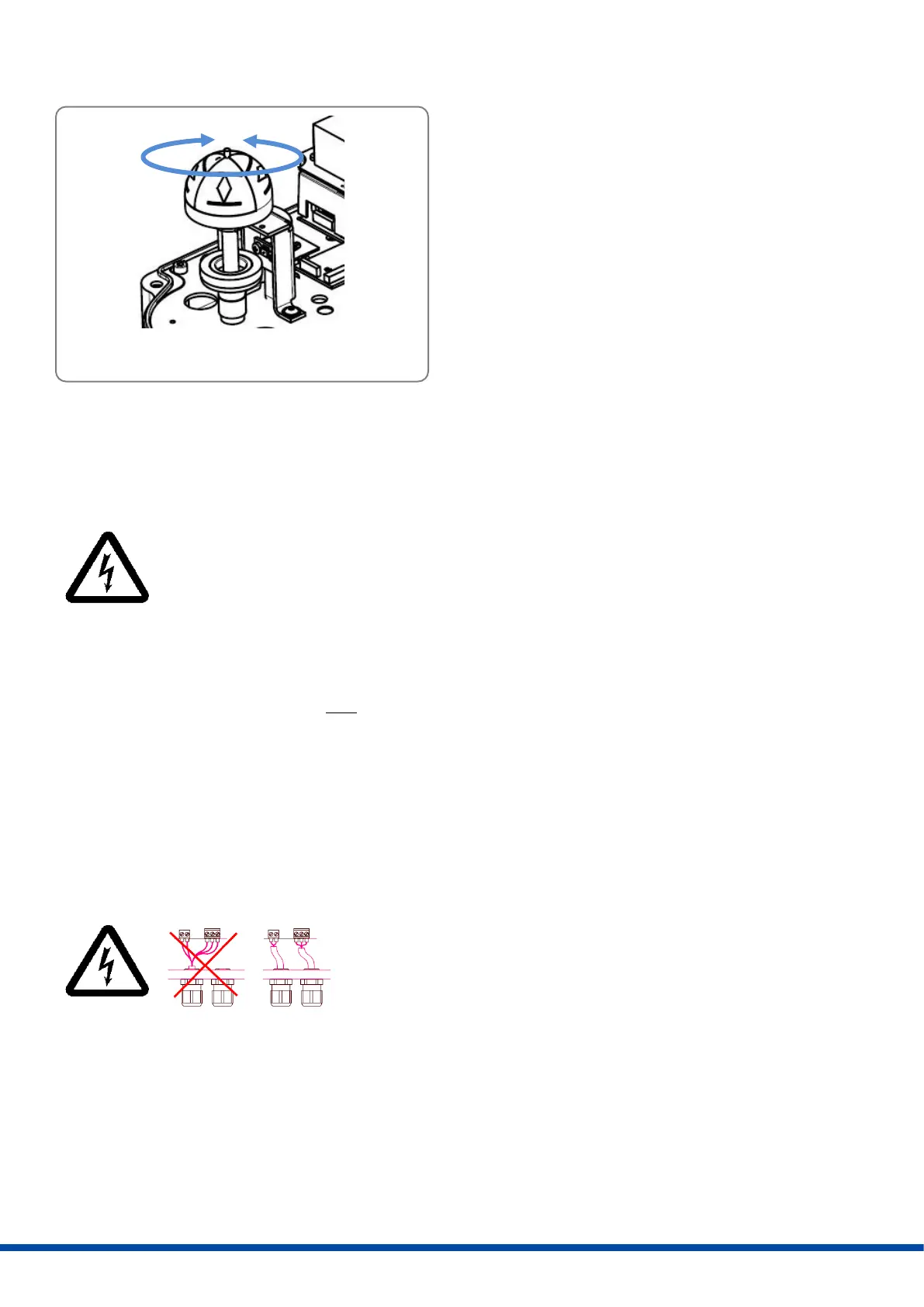
Please protect all of the power supply and control cables in front of the
terminals mechanically by using suitable measures against
unintentional loosening. Never install the power supply and the control
cables together in one line but instead please always use two different
lines.
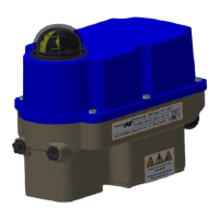
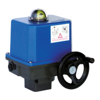
The position indicator is a two‐coloured half ball
turning under a transparent dome with
blackened quarter segments.
Take off the cover and turn the half ball as
appropriate to adjust the position indicator.
Figure 6: Adjustment of the position indicator