7. Valve mounting
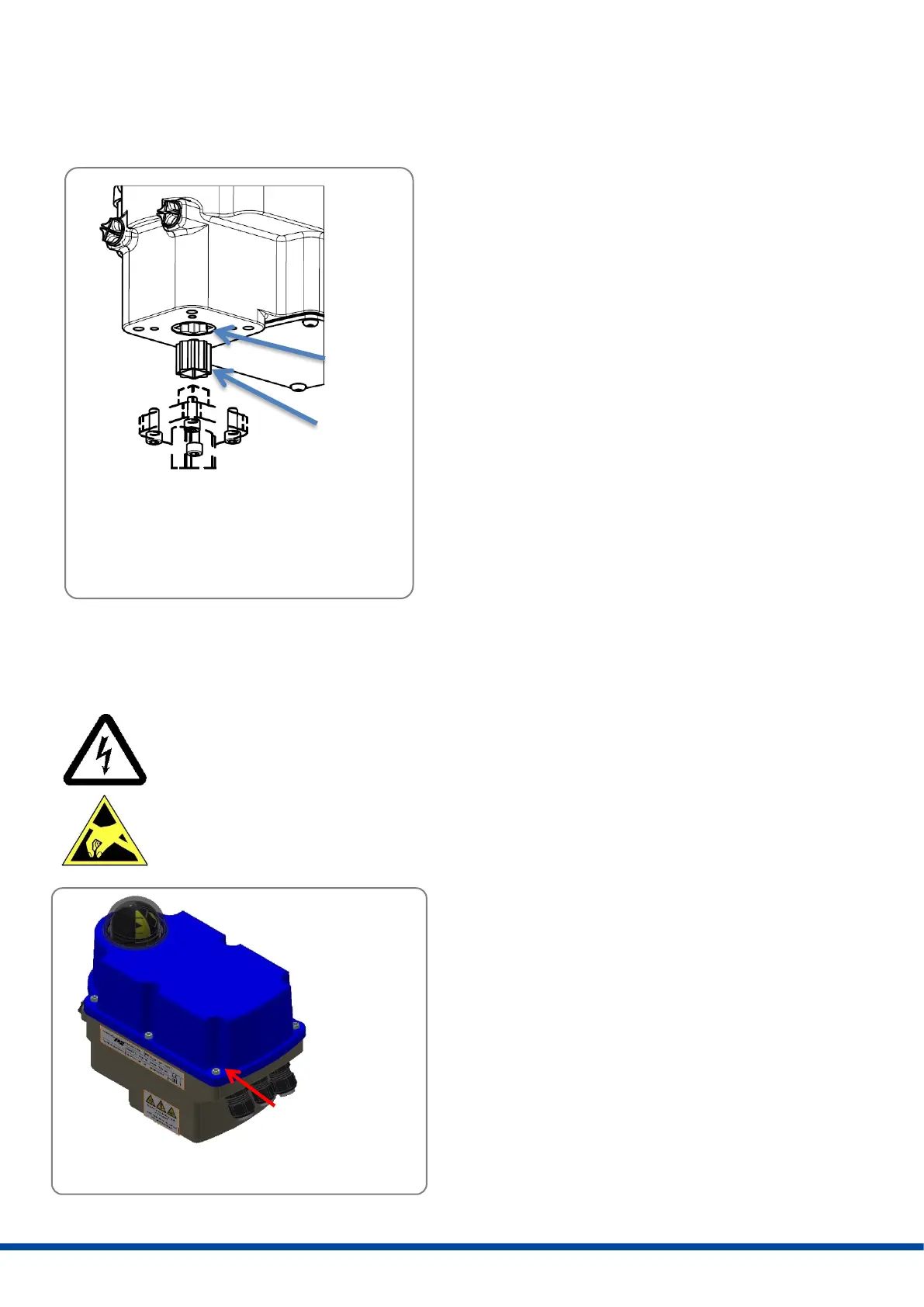
The PSF-Q actuators are designed with a mechanical interface according to ISO 5211 for valve mounting. The gear
contains an exchangeable drive bush to connect the actuator to the valve shaft.
• Check if the actuator flange suits the valve flange.
• Check whether the plug-in coupling of the actuator
matches the design of the valve shaft. If necessary,
commercially available adapters can be used to adapt to
the valve shaft.
• Connect the actuator electrically (see 10.).
• Position the actuator by means of manual operation
(see 11.7) so that it matches the position of the valve.
• Clean the surface of the connection components,
lubricate valve shaft slightly.
• Tighten the screws in a diagonal sequence according to
the required torque.
Figure 4: Actuator flange
8. Removing and closing the cover
Open the cover only in a dry environment.
Attention! Observe precautions for handling. Ground the actuator. Before opening the cover, touch
grounded housing parts.
Open:
Loosen the screws by using a screwdriver and unscrew
them entirely out of the gear casing. The screws are
protected against loss. Carefully remove the cover so that
the injected seal is not damaged.
Close:
Put the cover on the gear casing and press down slightly.
Tighten the screws gently and then crosswise.




 To Next Page