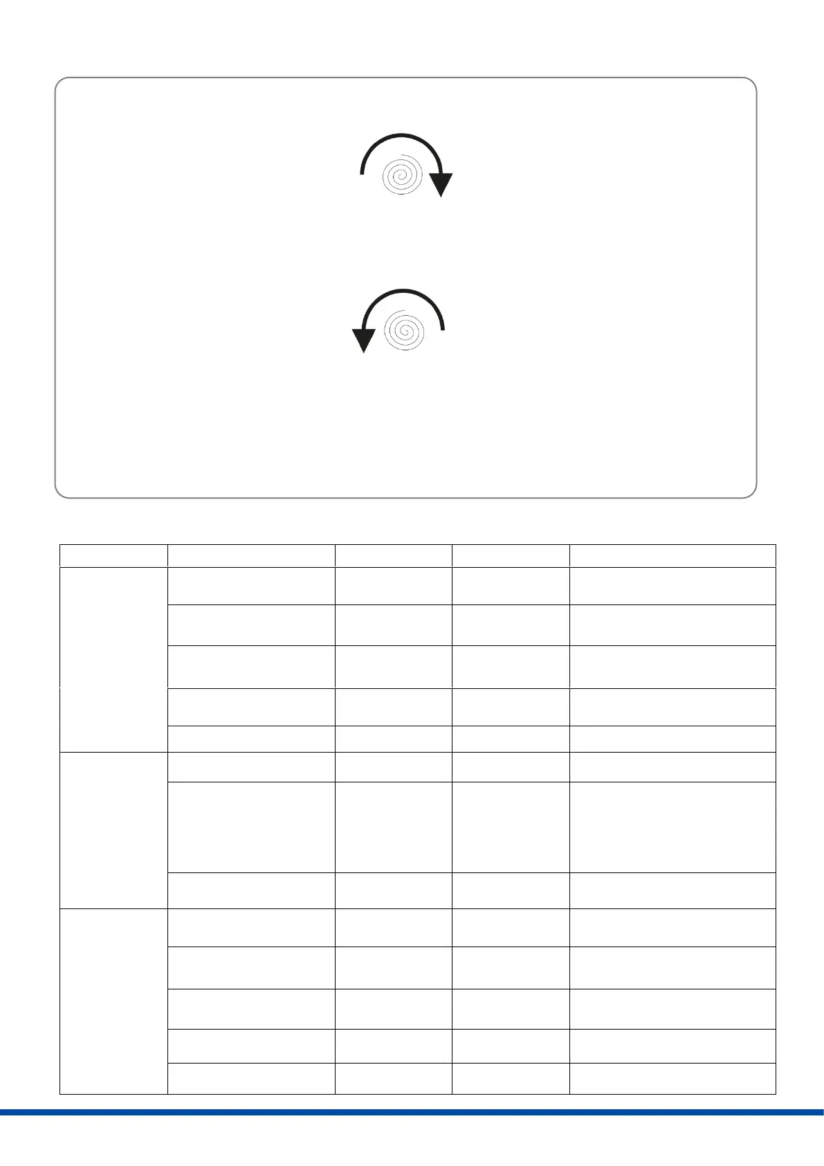
11.2 Operating direction
11.3 Operator push buttons
Both LEDs are flashing
alternately
Output valve shaft
clockwise (CW)
Output valve shaft
counterclockwise (CCW)
Both LEDs are flashing
alternately
Green LED is flashing 7x
(if commissioning is finished),
green LED is flashing quickly
(if commissioning failed)
Both LEDs are flashing
alternately
output valve shaft
clockwise (CW)
output valve shaft
counterclockwise (CCW)
Clockwise (CW) = Spring drives output valve shaft clockwise
Counter Clockwise (CCW) = Spring drives output valve shaft counterclockwise
Figure 8: Operating direction
Actuator CW
Spring drives output valve shaft CW
DIP switch S2.1 Off Travel end position Torque end position
DIP switch S2.1 On Torque end position Travel end position
Actuator CCW
Spring drives output valve shaft CCW
DIP switch S2.1 Off Travel end position Torque end position
DIP switch S2.1 On Torque end position Travel end position
 Loading...