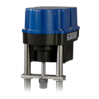
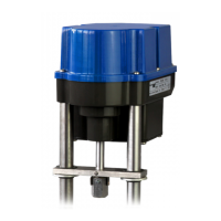
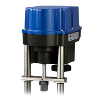
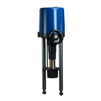
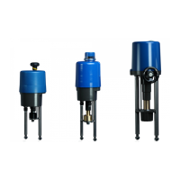
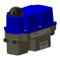
Mounting positions
Outdoor usage:
When using actuators in environments with high
temperature fluctuations or high humidity, we suggest a
heating resistor to be fitted to prevent the build-up of
condensation within the enclosure.
Figure 2: Mounting positions
5. Function
The PSF-Q electric actuators are designed for the operation of 90° quarter-turn actuators. For mechanical connection
to the valve, the actuators are equipped with flanges according to ISO 5211.
The torque generated by a brushless DC motor (BLDC) is transmitted via a multi-stage spur gear spur gearbox to a
coupling with double square drive. This serves as a connecting element to the valve shaft. The mechanical limitation
of the rotation angle is continuously adjustable by ±5° in one end position. The rotation angle is measured and
controlled by a linear 12 Bit Hall sensor.
In case of mains power loss, the stroke movement is in OPEN or CLOSE direction by spring force.
Electrical wiring is done to a terminal block under the actuator cover.
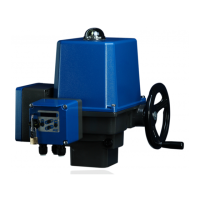
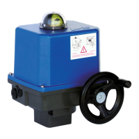
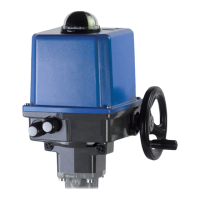
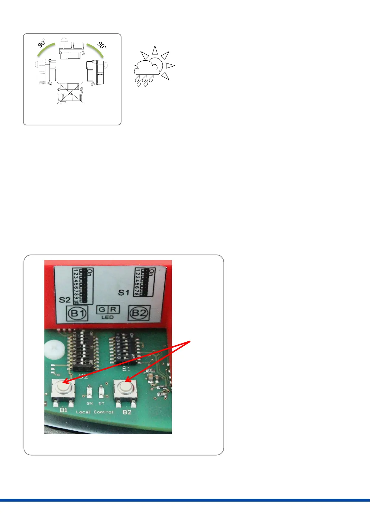
6. Manual operation
Figure 3: Manual operation
For commissioning the actuator
during adjustment work (valve
mounting and end position
adjustment), an electrical manual
override by means of a push-button
is available (see 11.7).