PS Engineering
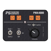
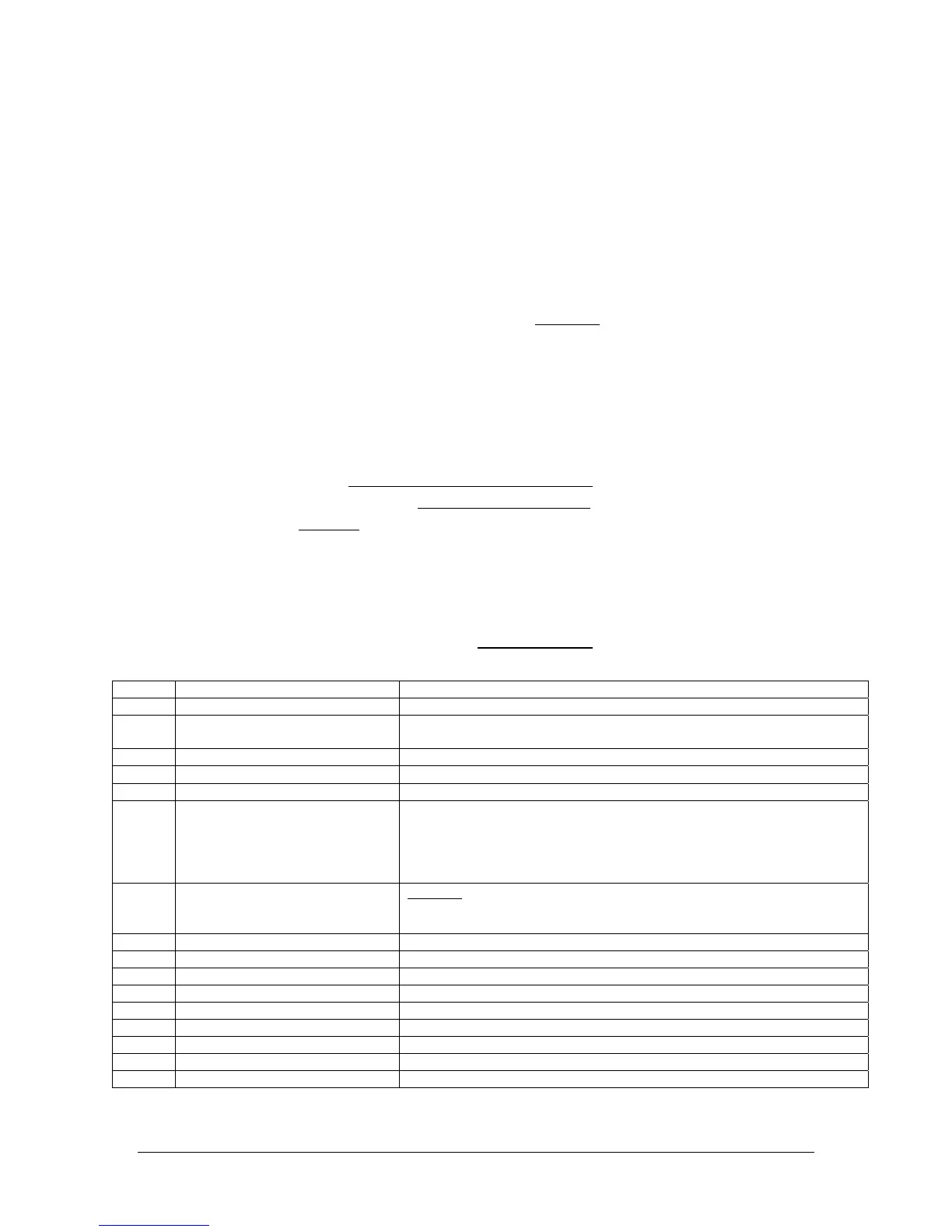
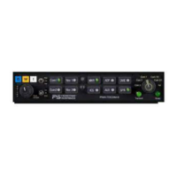
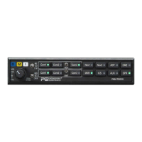
PMA4000 Series Audio Selector Panel and IntelliVox™ Intercom System
Installation Manual
200-041-0002 Appendix D Rev 5, March 2007
Appendix D -Instructions for FAA Form 337 and Continuing
Airworthiness
Example for FAA Form 337
One method of airworthiness approval is through an FAA Form 337, Major Repair and
Alteration (Airframe, Powerplant, Propeller, or Appliance) In the case of the PMA4000
TSO (11942, only) audio panel you may use the following text as a guide.
Installed FAA-TSO Approved 4-place intercom/audio selector panel, PS Engi-
neering PMA4000, part number 11942 at station . Installed per AC43.13-
2, Chapter 2, paragraph 23 (Instrument Panel Mounting). Installed per PS Engi-
neering Installation Operators Manual P/N 200-041-_______, revision (X), dated
_____, _______.
Interface to existing aircraft radios in accordance with installation manual and in
compliance with practices listed in AC43.13-2, Chapter 2. All wires are Mil-Spec
22759 or 27500. Connection to the aircraft dimmer bus is accomplished per the
installation manual and . Power is supplied to the
unit through a 1A circuit breaker (type and part number), and total electrical load
does not exceed % of the electrical system capacity with the PMA4000
added.
Aircraft equipment list, weight and balance amended. Compass compensation
checked. A copy of the operation instructions, contained in PS Engineering docu-
ment 200-041-_______, revision _, ______ is placed in the aircraft records. All
work accomplished listed on Work Order .
Sample ICA Checklist for PS Engineering Audio Panels:
Section Item Information
1 Introduction Installation of audio control panel and intercommunications system.
2 Description Installation as described in manufacturer’s installation manual referenced on
FAA Form 337, including interface with other avionics audio as required.
3 Controls See installation and operator’s guide referenced on FAA Form 337.
4 Servicing None Required
5 Maintenance Instructions On Condition, no special instructions
6 Troubleshooting In the event of a unit problem, place the unit into “off,” “fail-safe” and/or
“emergency” mode. This allows pilot communications using COM 1. Follow
checkout instructions in the installation manual referenced on the FAA Form
337. For a specific unit fault, contact the manufacturer at (865) 988-9800 for
special instructions.
7 Removal and replacement informa-
tion
Removal: Remove knobs. Using a Philips screw drier, carefully remove the 2
screws through the face plate. The unit is then removed from the rear.
Installation, Reverse installation procedure.
8 Diagrams Not applicable
9 Special Inspection Requirements Not Applicable
10 Protective Treatments Not Applicable
11 Structural Data Not Applicable
12 Special Tools None
13 Not Applicable Not Applicable
14 Recommended Overhaul Periods None
15 Airworthiness Limitations Not Applicable
16 Revision To be determined by installer