Tel : 886-2-29162151
Fax: 886-2-29174598
VFD Driver/Controller IC PT6315
PT6315 v2.0 Page 10 Sep. 2002
LED Display
PT6315 provides 4 LED Display Terminals, namely LED1 to LED4. Data is written to the LED
Port starting from the least significant bit (b0) of the port using a WRITE Command. Each bit
starting from the least significant (b0) activates a specific LED Display Terminal -- b0
corresponds LED1 Display, b1 activates LED2 and so forth. Since there are only 4 LED display
terminals, bits 5 to 8 (b4 ~ b7) are not used and therefore ignored. This means that b4 to b7
does NOT in anyway activate any LED Display, they are totally ignored.
When a bit (b0 ~ b3) in the LED Port is “1”, the corresponding LED is OFF. Conversely, when
the bit is “0”, the LED Display is turned ON. For example, Bit 1 (as designated by b0) has the
value of “1”, then this means that LED1 is OFF. It must be noted that when power is turned
ON, bit 1 to bit 4 (bo to b3) are given the value of “0” (all LEDs are turned ON). Please
refer to the diagrams below.
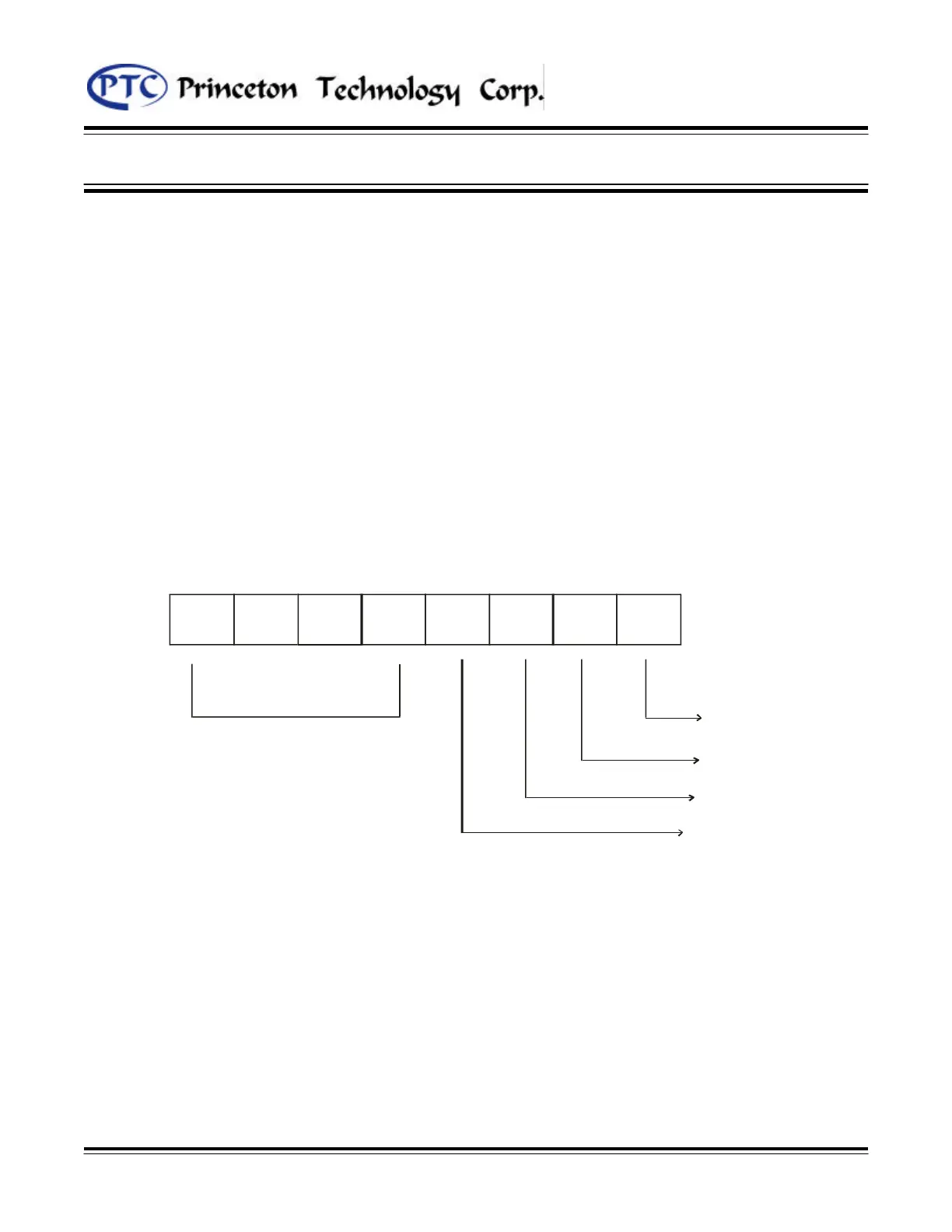
Figure 8: PT6315 LED Display Designation
-
b3 b2
b1 b0
--
-
NOT USED