EasyManua.ls Logo

PTF 3203A - Control, Monitor, and Alarm Connections

PTF 3203A
51 pages
Print Icon
To Next Page IconTo Next Page
To Previous Page IconTo Previous Page
Loading...
4.7. Control/Monitor/Alarm Relay Connections
Control and monitoring is available through an RS232 port (female 9-
contact D connector) and over an Ethernet port (RJ45 connector). The
RS232 port is configured as DTE, receiving data on pin 3 and transmitting
data on pin 2. Pin 5 is chassis ground, and the other lines are unused.
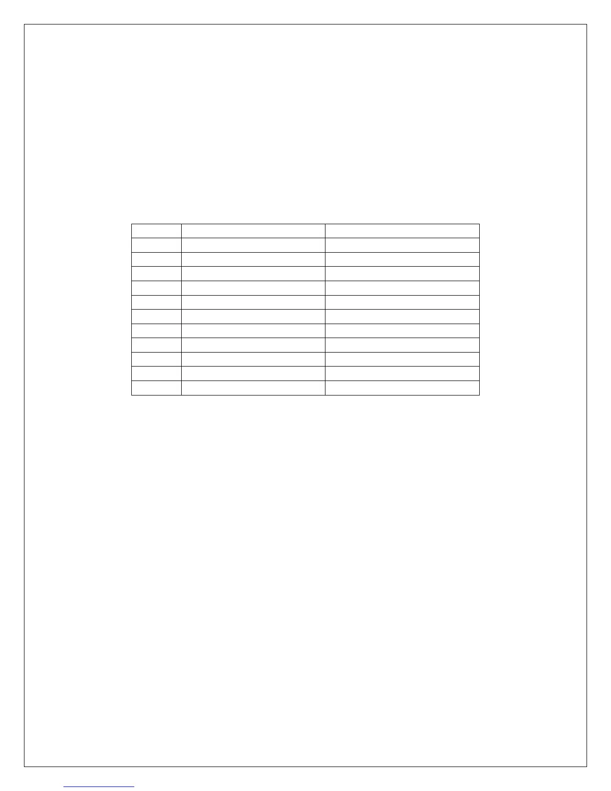
DB9 Connector
Pin #
Function
Comments
1
Alarm Relay NO
Closed when in alarm
2
TX Data (RS232)
3
RX Data (RS 232)
4
Alarm Relay NC
Open when in alarm
5
Ground (RS232)
6
Alarm Relay Common
7
8
9