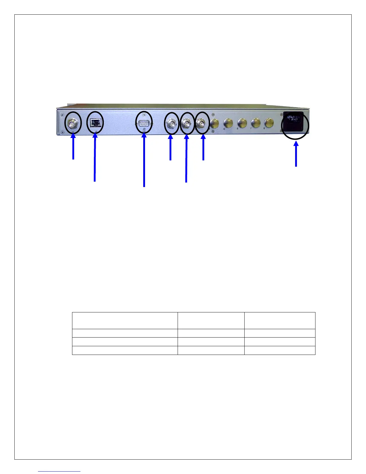
4.8. Connection Diagram
ptf 3203A standard output/input connections are as shown in the picture
below:
Note:
If your unit(s) is configured with optional outputs please refer to
APPENDIX in the back of this manual.
The table below shows the relationship between the firmware terminology
and the physical output connector positions on the rear of the unit:
10 MHz sine wave (hard wired)
10MHz
1PPS
IRIG-B
100 to 240
VAC IN
DB9
Serial I/O
Control/Monitor
J2
RJ-45
Ethernet
TNC
 Loading...