12286 Rev 2 Page 2of 3
4.1 Operation
Manual Mode Flow Set Point Changes
Follow the steps below to change the SENTRY 9000 set point. The Sentry system is configured
to measure and display flow set points in units of cubic feet per minute.
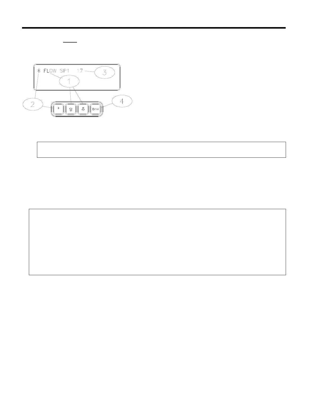
• Using the up [á] or down [â] arrow keys on the
SENTRY TIM-100/120 keypad, scroll through
the menu parameters until “FLOW SP1” is
shown in the top left corner of the display.
‚ Choose the menu item by pressing on the star
[*] key.
ƒ Using the up [á] or down [â] arrow keys on the
SENTRY TIM-100/120 keypad, change the
displayed value to the desired value.
„ Press the enter [ENT] key to confirm selection.
Note:
• For the SENTRY 9000, a displayed value of 35 = 35 CFM.
Analog Interfaced Operation
When the SENTRY system is configured for analog operation, the process exhaust pressure or
flow set points are entered through the process equipment. The analog interface operates on a
standard 0 to 5-volt full-scale command signal.
Note:
• The menu item “STPTMODE” must be set to “ANALOG” in order to use analog
communication. Refer to Section 2, page3 for details.
• The menu item “AUX IN” will reflect the voltage received at the SENTRY TIM-100/120.
There is an implied decimal point to the left of the third digit (5000 = 5.000 volts).
• The voltage indicated by the “AUX IN” should be within ± .02 volts of the analog voltage
signal transmitted by the process tool.
• Both the analog ground and power ground leads must be connected to the TIM-
100/120 and be common on the process tool.
The following table illustrates how the set point and read-back analog voltage signals are
interpreted within the TIM-100/120.