12286 Rev 2 Page 2 of 5
5.1 Serial Communication Interface Programming
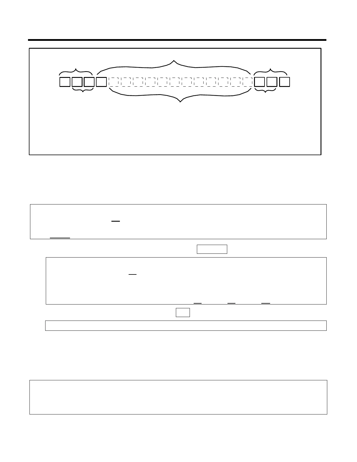
Start of message
Address of controller to
receive the message
Command
Command qualifiers [position] and [data]
Check sum
>
End of message
↵
Beginning
Middle
End
Power-Up Clear Using Command “A”
Once power has been applied to the TIM-100/120, a power-up clear command is required to
initialize communications between the host and the TIM-100/120. This command only
functions if it is the first command sent after power-up and prevents the TIM-100/120 from
returning a “power-up clear expected” error.
Note:
• This command has no effect on the TIM-100/120 operation.
• After a power up clear command is issued, the TIM-100/120 resets to the last
saved menu parameter settings.
Host to TIM-100/120 Command Message: >00AA1↵
Function: This message sends a power-up clear command to the TIM-100/120 at base
address 00 (>00AA1↵).
Note:
• If additional TIM-100/120s were connected on the same network, each base address
would be incremented by four. Example: >04AA1↵, >08AA1↵, >0CAA1↵, etc.
TIM-100/120 to Host Response: >A↵
Function: This response indicates an acknowledgement without error.
Set Point Using Command “S”
A set point command must be sent to the TIM-100/120 in order to command the process
exhaust controller to a new set point. Depending on whether the exhaust controller is a
pressure or flow controller, one of two memory locations must be addressed for this command.
A mask is used to define the memory location.
Note:
• A set point or read-back can be resolved to a 12-bit value (0 to 2
12
- 1) with hexadecimal
representation of 000 to FFF (0 to 4095 decimal). The value is scaled relative to full-
scale pressure or full-scale flow.