Jun. 2020 / Rev.0.1 DS-UB40.241-EN All values are typical figures specified at 24Vdc input voltage, 40A output current in
power supply mode at 25°C ambient, no charging and after a 5 minutes run-in time unless otherwise noted.
www.pulspower.com Phone +49 89 9278 0 Germany
DC-UPS. The user has to take care by himself to stay below the allowed output
currents in order not to overload the unit.
Output short circuit current in
power supply mode
Corresponds to the short-circuit current of the power supply or the current
limitation of an input fuse, if installed.
Overload behavior in battery mode
Tripping delay in battery mode
At 60A
At 70A
At 100A
At shorted output
Leakage current to the input of the DC-UPS in battery mode
The unit is resistant and does not show malfunctioning when a
load feeds back voltage to the DC-UPS. It does not matter
whether the DC-UPS is on or off.
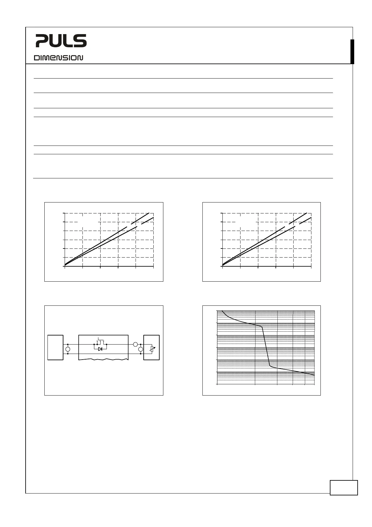
Fig. 5-1 Input to output voltage loss,
typ.
Fig. 5-2 Battery input to output voltage loss, typ.
Input to Output Voltage Loss, typ.
0mV
20A
25mV
50mV
75mV
100mV
50A40A
Output Current
0
125mV
AB
A... 25°C
B... 60°C
10A 30A
150mV
Battery input to Output Voltage Loss, typ.
0mV
20A
50mV
100mV
150mV
200mV
50A40A
Output Current
0
250mV
AB
A... 25°C
B... 60°C
10A 30A
300mV
Fig. 5-3 Voltage loss measurement setup
Fig. 5-4 Overload current in battery mode,
(tripping characteristic) typ.
V
Power
Supply
+
-
U
IN
Voltage Loss
U
IN
=
U
OUT
-
A
V
I
OUT
U
OUT
Variable
Load,
0-25A
UB40.241
Input Output
Output Current, typ.
50A
10µs
100µs
1ms
10ms
0.1s
1s
10s
100A
150A 200A 300A
 Loading...