Do you have a question about the Pulseroller EZ-Qube-N and is the answer not in the manual?
Explains symbols used throughout the manual for clear communication.
Provides critical safety, handling, and ESD precautions for module operation and maintenance.
Lists contact information for technical and sales support from Pulseroller.
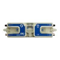
Identifies and describes the physical components and connectors on the EZ-Qube module.
Specifies the physical dimensions and mounting considerations for installing the EZ-Qube module.
Details the power connector plug, wire size, strip length, and pin assignments.
Describes the 9-pin JST style motor port and its pinout for connecting motors.
Explains the I/O terminal block, its pinout, and the function of each signal.
Provides guidelines for routine inspection and safe cleaning of the EZ-Qube module.
Lists key technical specifications including input requirements, current limits, and environmental ratings.
Details power supply requirements, grounding, and sizing considerations for the EZ-Qube.
Explains the importance and methods for correct motor and frame grounding.
Covers wiring for Run and Reverse inputs, compatible with PNP and NPN signal sources.
Describes wiring and configuration for using a 0-10V analog signal for speed control.
Details wiring for PNP versions of the EZ-Qube, focusing on output signal polarity.
Details wiring for NPN versions of the EZ-Qube, focusing on output signal polarity.
Explains the functions of the CONFIG DIP switch for speed range, rotation, and error reset.
Provides tables for SPEED DIP switch settings, linking them to motor RPM and speed outputs.
Details how to set acceleration and deceleration ramp times using the ACC/DEC DIP switches.
Describes the pulse speed output signal and its relationship to motor speed.
Explains the error output signal and the status indicated by module LEDs.
| Brand | Pulseroller |
|---|---|
| Model | EZ-Qube-N |
| Category | Controller |
| Language | English |