DE
EN
DE
EN
3. Spezifi kationen
4. Standard Verpackung WHD100 / WHD100M4
Unterstützte Video Formate
TV: 1080p, 1080i, 720p, 576p, 480p
Unterstützte Audio Formate PCM, DTS, DOLBY DIGITAL
Drahtlose Kommunikation MIMO
Modulationsverfahren OFDM
Maximale Sendeleistung 12dBm
Maximale Übertragungsdistanz
20 Meter auf freiem Feld und 10
Meter durch Wände
Bild Verzögerung < 1ms
Antenne Integrierte Hochleistungsantenne
Betriebsfrequenz 5.1GHz bis 5.9GHz
IR Frequenz 38KHz
Stromversorgung
AC In 100~240V, DC Out 5V / 2.5A
Stromadapter
Betriebstemperatur 0°C bis 40°C
WHD100 WHD100M4
Wireless HD AV Sendeeinheit (TX) 1x 1x
Wireless HD AV Empfängereinheit (RX) 1x 1x
5 V / 2,5 A Stromadapter für TX und RX 2x 2x
HDMI Verbindungskabel 1,2m 1x 1x
4x2 HDMI Matrix - 1x
Fernbedienung für HDMI Matrix - 1x
IR Kontrollbox - 1x
5 V/1A DC Stromadapter für
IR Verstärker Box
- 1x
Infrarot Verlängerung 1,5m 1x 4x
Bedienungsanleitung 1x 1x
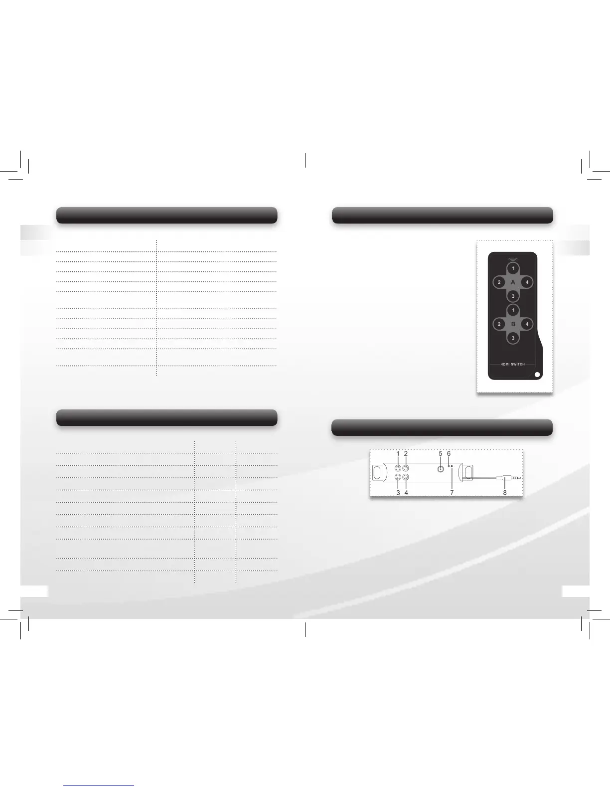
5.3.2 Remote Control
1. A-1 Select HDMI IN 1 device. Connect
HDMI IN 1 to HDMI OUT A Channel.
2. A-2 Select HDMI IN 2 device. Connect
HDMI IN 2 to HDMI OUT A Channel.
3. A-3 Select HDMI IN 3 device. Connect
HDMI IN 3 to HDMI OUT A Channel.
4. A-4 Select HDMI IN 4 device. Connect
HDMI IN 4 to HDMI OUT A Channel.
5. B-1 Select HDMI IN 1 device. Connect
HDMI IN 1 to HDMI OUT B Channel.
6. B-2 Select HDMI IN 2 device. Connect
HDMI IN 2 to HDMI OUT B Channel.
7. B-3 Select HDMI IN 3 device. Connect
HDMI IN 3 to HDMI OUT B Channel.
8. B-4 Select HDMI IN 4 device. Connect
HDMI IN 4 to HDMI OUT B Channel.
5.3.2 IR Kontrollbox
Note: You only need to use the IR Extender Box when you use the Trans-
mitter unit with the HDMI Switch.
1-4 IR: Connect up to 4 HD media devices with enclosed IR extension ca-
bles. Place the IR fl asher on the extension cables close to the IR receivers
of the media devices.
5 DC IN: Connect with the power supply
(enclosed 5V/1A Power Adapter).
6 Link Indicator: Indicate IR signal connection.
7 Power Indicator: Indicate when the extension box is powered on.
8 IR Plug: Connect with IR port on the Switch (16 in Image 3).
Bild 5
04 17
 Loading...