Home
Putzmeister
Water Pump
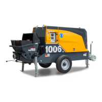
BSA 1006 D5
Putzmeister BSA 1006 D5 - User Manual
380 pages
Manual
Specs
Ask a question
Save Page as PDF
To Next Page
To Next Page
Loading...
Operating Instructions
for machine operator and maintenance staff
always keep by the machine
Translation of the original instructions
Stationary concrete pump
BSA 1006 D5
Machine no.
210111697
2021-08-09
The paper on which this document is printed is 100% chlorine-free
© Putzmeister Concrete Pumps GmbH 2021
2
Table of Contents
Main Page
Operating Instructions
1
Table of contents
5
1 Guide to the Operating Instructions
11
1.1 Foreword
13
1.2 Icons and symbols
14
1.2.1 Layout of warning notices
15
2 Safety regulations
17
2.1 Definition of terms
19
2.1.1 Machine
19
2.1.2 Concrete pump
19
2.1.3 Arm assembly
19
2.1.4 Placing boom
19
2.1.5 Base structure
19
2.1.6 Truck mixer
20
2.1.7 Delivery line systems
20
2.1.8 End hose
20
2.1.9 Manufacturer
20
2.1.10 Operator
20
2.1.11 Machine operator
20
2.1.12 Hoseman
20
2.1.13 Signaller and other auxiliary personnel
21
2.1.14 Truck mixer driver
21
2.1.15 Subject expert
21
2.1.16 Qualified personnel
21
2.1.17 After Sales Service personnel
21
2.1.18 Maintenance
21
2.1.19 Place of work, working area, danger zone
22
2.1.19.1 Mobile machines
22
2.1.19.2 Stationary machines
22
2.1.19.3 Place of work
24
2.1.19.4 Working area
24
2.1.19.5 Danger zone
25
2.2 Designated use
26
2.2.1 Retesting (safety inspection)
27
2.2.2 Inspection intervals for retesting
27
2.3 Improper use
28
2.3.1 Transporting goods
28
2.3.2 Lifting loads
29
2.3.3 Removing obstacles
29
2.3.4 Extending the reach
29
2.3.5 Extending the placing boom and end hose
29
2.3.6 Impermissible end hose
30
2.3.7 Impermissible working area
30
2.3.8 Climbing the placing boom
31
2.3.9 Highpressure delivery
31
2.3.10 Accessories and attachments
31
2.3.11 Changes to the machine
31
2.4 Exclusion of liability
32
2.5 Personnel
32
2.5.1 Requirements
32
2.5.2 Qualifications
33
2.5.3 Responsibility of the machine operator
33
2.6 Operating Instructions, operating procedures and other regulations
33
2.6.1 Operating Instructions
33
2.6.2 Operating procedures
34
2.6.3 Other regulations
35
2.7 Personal protective equipment
35
2.8 Before working with the machine
37
2.8.1 Checking that the machine is ready for operation
37
2.8.2 Rendering the machine ready for operation
37
2.9 Danger due to high voltage
38
2.9.1 High-voltage lines
38
2.9.2 Discharge voltage pattern
38
2.9.3 Clearances
38
2.9.4 Highvoltage warning devices
40
2.9.5 Procedure in the event of a flash over
40
2.9.6 Earthing in the event of electrostatic charging
41
2.9.7 Earthing on construction sites with special installations
41
2.10 Stationary machines
41
2.10.1 Setup site
41
2.10.2 Stationary placing booms
42
2.10.3 Lifting machines and components
42
2.10.4 Loading and transporting
42
2.11 Mobile machines
43
2.11.1 Setup site
43
2.11.2 Supporting ground
44
2.11.3 Corner bearing loads
45
2.11.4 Supports
45
2.11.5 Driving
47
2.11.6 Towing
48
2.11.7 Loading
48
2.12 Placing booms
49
2.12.1 Unfold placing boom
49
2.12.2 End hose
51
2.12.3 Guiding the end hose ergonomically
52
2.12.4 Connecting drills
52
2.12.5 Procedure in storms
52
2.12.6 Concreting in cold weather
53
2.13 Delivery line systems
53
2.13.1 Suitable delivery lines
53
2.13.2 Securing delivery lines
54
2.13.3 Leak tightness and blockages
54
2.13.4 Opening delivery lines
55
2.13.5 Clearance to delivery lines
55
2.13.6 Securing the delivery lines
55
2.13.7 Continuation delivery lines
55
2.13.8 Devices for shutting off, diverting and cleaning
56
2.14 Pumping operations
56
2.14.1 Place of work
56
2.14.2 Safety
56
2.14.3 Remote control
57
2.14.4 Moving machine components and hot surfaces
57
2.14.5 Constant observation of the machine
58
2.14.6 Truck mixer
58
2.15 Cleaning
58
2.15.1 General
58
2.15.2 Cleaning agents
59
2.15.3 Cleaning with compressed air
60
2.15.4 Protection against water
62
2.15.5 Post-cleaning procedure
62
3 General technical description
63
3.1 Overviews
65
3.2 Safety equipment
67
3.2.1 Overview
67
3.2.2 Safety components
68
3.2.3 Safety-related parts (SRPs)
68
3.2.4 Plates
70
3.2.4.1 Check function
70
3.2.5 EMERGENCY STOP function
70
3.2.5.1 Function
70
3.2.5.2 Positions of the EMERGENCY STOP buttons
71
3.2.5.3 Deactivating the EMERGENCY STOP
71
3.2.5.4 Checking the EMERGENCY STOP function
71
3.2.6 Agitator safety cutout
73
3.2.6.1 Structure
74
3.2.6.2 Function
74
3.2.6.3 Deactivating the agitator safety cutout
75
3.2.6.4 Checking the agitator safety cutout
76
3.2.7 Grille
78
3.2.7.1 Check wear
78
3.3 General conditions for using the machine
79
3.3.1 Service life
79
3.3.2 Site of use
80
3.3.3 Operating altitude
80
3.3.4 Operating temperature
80
3.4 Machine rating plate
81
3.5 Sound pressure level/sound power level
82
3.5.1 Sound pressure level
82
3.5.2 Sound power level
83
3.6 Electromagnetic compatibility (EMC)
83
3.7 Putzmeister Connected Services
83
3.7.1 Remote Service
84
3.7.2 Machine Cockpit
84
3.8 Exhaust after treatment
84
3.8.1 Function
84
3.8.2 Regeneration
85
3.8.3 Starting regeneration
85
3.9 Colour definition – LEDs in the button
87
3.10 Control cabinet
88
3.11 Core pump operating panel
89
3.12 Display
91
3.13 Software
92
3.13.1 Main menu
92
3.13.1.1 Navigation bar
93
3.13.1.2 Menu content
94
3.13.1.3 Function bar
95
3.13.2 “User settings” menu
96
3.13.3 “Core pump” menu
97
3.13.4 “Motor” menu
100
3.13.4.1 Motor fault codes
102
3.13.5 “Inputs and outputs” menu
103
3.13.6 “Operating data” menu
104
3.13.7 Messages
105
3.13.7.1 Entire machine
106
3.13.7.2 Motor
106
3.13.7.3 Core pump
108
3.14 Cable remote control
109
3.14.1 Structure
109
3.14.2 Safely using the remote control
110
3.15 Core pump
111
3.15.1 Structure
111
3.15.2 Function
112
3.15.3 Reversal
112
3.15.4 Water box
113
3.15.4.1 Structure
113
3.15.4.2 Function
113
3.15.4.3 Filling the water box
114
3.15.4.4 Draining the water box
115
3.15.5 Agitator
116
3.15.5.1 Structure
116
3.15.5.2 Function
116
3.15.5.3 Operating the agitator
117
3.15.6 Vibrator
118
3.15.7 Magnetic switch distributor casing
119
3.15.7.1 Structure
119
3.15.7.2 Function
119
3.15.7.3 Indicator lights
120
3.15.8 Magnetic switch connector
121
3.15.8.1 Significance of the LEDs
121
3.16 Centralised lubrication system
123
3.16.1 Structure
123
3.16.2 Function
123
3.16.3 Maintaining the centralised lubrication system
124
3.16.4 Filling the lubricant reservoir
124
3.16.4.1 Filling the lubricant reservoir using a grease gun
125
3.16.5 Additional lubrication procedure
125
3.17 Flushing water pump
126
3.17.1 Structure
126
3.17.2 Function
126
3.17.3 Switching on the water pump
127
3.17.4 Switching off the water pump
128
3.17.5 Draining the flushing water pump
129
4 Transport, support and connection
131
4.1 Transporting
133
4.1.1 Loading
133
4.1.2 Driving
135
4.2 Supporting the machine
135
4.2.1 Checking the setup site
135
4.2.1.1 Minimum clearance from pits
136
4.2.1.2 Safe clearance from pits
138
4.2.1.3 Supporting ground
139
4.2.2 Support structure
140
4.2.3 Extend supports
141
4.2.3.1 Setting up the machine
141
4.2.3.2 Lowering the rear support feet
142
4.2.3.3 Folding down the support foot
144
4.2.3.4 Lowering the forward support foot
145
4.2.4 Retracting the supports
146
4.3 Connecting the water supply
146
5 Operation
149
5.1 Test run
151
5.2 Starting up
151
5.2.1 Checking the machine for damage
151
5.2.2 Draining the hydraulic fluid reservoir
153
5.2.3 Checking functional fluids
154
5.2.4 Switching on the machine
155
5.2.5 Warming up the hydraulic fluid
156
5.2.6 Deactivating the EMERGENCY STOP
156
5.2.7 Deactivating the agitator safety cutout
157
5.3 Checking the functions
157
5.3.1 Checking the EMERGENCY STOP function
158
5.3.2 Checking the agitator safety cutout
159
5.3.3 Checking the pump functions
161
5.3.3.1 Checking the switchover
161
5.3.3.2 Magnetic switch
161
5.3.3.3 Checking the stroke length
161
5.3.3.4 Checking the stroke time
162
5.3.4 Checking the hydraulic fluid filters
162
5.3.4.1 Check the contamination indicator
163
5.3.4.2 Checking the pressure filter
163
5.4 Hand signals for pumping operations
164
5.4.1 EMERGENCY STOP hand signal
165
5.4.2 Hand signal for stopping
165
5.4.3 Hand signal for increasing output/start of delivery
166
5.4.4 Hand signal for reducing output
166
5.4.5 Hand signal for reverse pumping
167
5.4.6 Hand signal for stopping the pump
167
5.5 Filling the water box
167
5.6 Pumping
168
5.6.1 Dangers during pumping
168
5.6.1.1 Sucking in air
168
5.6.2 Notes on correct pumping
169
5.6.3 Mixing together
169
5.6.4 Operating the agitator
170
5.6.5 Starting to pump
170
5.6.6 Starting the pumping process
172
5.6.7 Checking the condition of the machine
172
5.6.8 Breaks in pumping
172
5.6.9 Rectify any faults
173
5.6.9.1 Blockage
173
5.6.9.2 Motor overload
174
5.6.9.3 Overheating
174
5.7 Cleaning
177
5.7.1 Observe the notes on cleaning
179
5.7.2 Cleaning preparations
179
5.7.2.1 Pre-fitting the catch basket
180
5.7.2.2 T delivery pipe with wash-out port
180
5.7.2.3 Wash-out adaptor
181
5.7.2.4 Preparing cement bags
183
5.7.2.5 Marking the water hose
183
5.7.3 Using concrete residue
184
5.7.3.1 Transporting concrete residue with a sheet
184
5.7.3.2 Disposing of concrete residue
185
5.7.4 Switching on the water pump
185
5.7.5 Clean the delivery line
187
5.7.5.1 Overview of the cleaning methods
187
5.7.5.2 Suction cleaning
189
5.7.5.3 Cleaning with pressurised water
193
5.7.5.4 Cleaning with compressed air
195
5.7.6 Cleaning the core pump
200
5.7.6.1 Draining concrete residue
200
5.7.6.2 Draining the water box
201
5.7.6.3 Cleaning the hopper
202
5.7.6.4 Spraying out the delivery cylinder
203
5.7.6.5 Checking the wear ring
204
5.7.6.6 Cleaning the gap between the transfer tube bearing and the transfer tube
205
5.7.6.7 Close hinged elbow
207
5.7.7 Cleaning the remote control
208
5.7.8 Cleaning other machine components
208
5.7.9 Switching off the water pump
209
5.8 Storing the machine
209
5.8.1 Document the measures taken to preserve value
210
5.8.2 General measures to preserve value
210
5.8.3 General measures to preserve the value of the electrical system assembly
210
5.8.3.1 Measures for preserving the value of Deutz engines with an electronic engine governor
211
5.8.3.2 Measures to preserve the value of the electrical system assembly (general)
211
5.8.4 General measures to preserve the value of the water assembly
212
5.8.5 General measures to preserve the value of the engine assembly
212
5.8.6 General measures to preserve the value of the concrete pump assembly
212
5.8.7 General measures to preserve the value of the hopper assembly
212
Glossary
213
1 Symbols for concrete pumps in accordance with German Mechanical Engineering Association Standard (VDMA -24119)
215
2 Abbreviations and technical terms
222
Index
231
Service Instructions
237
Table of contents
241
1 Guide to the Service Instructions
243
1.1 Foreword
245
1.2 Icons and symbols
246
1.2.1 Layout of warning notices
247
2 Safety regulations
249
2.1 Basic principle
251
2.1.1 Exclusion of liability
251
2.2 Requirements for special work
251
2.3 Welding
252
2.4 Working on the placing boom
253
2.5 Safetyrelevant components
254
2.6 Software
254
2.7 Protective and safety equipment
254
2.8 Electrical power
255
2.8.1 General
255
2.8.2 Electrical components
256
2.8.3 Power at the construction site
256
2.9 Hydraulic systems
256
2.9.1 General
256
2.9.2 Replacing hydraulic hoses
258
2.10 Noise emissions
258
2.11 Exhaust fumes
258
2.12 Functional fluids
259
2.13 Disposal of the machine
260
3 Special operating modes
261
3.1 Recovery with onboard equipment
263
3.1.1 Preparing for recovery
263
3.1.2 Setting up the pump control system
264
3.1.3 Emergency operation of the core pump
264
4 Maintenance
267
4.1 Maintenance intervals
269
4.2 Residual risks during maintenance, inspection and repair work
271
4.2.1 Personal protective equipment
271
4.2.2 Personnel requirements
271
4.2.3 Auxiliary devices
271
4.2.4 Residual risks
272
4.3 Specifications for bolted connections
274
4.4 General tightening torques
274
4.4.1 Set screws and nuts
275
4.4.2 Fitting threaded unions
275
4.4.3 Reassembly of WALFORMplus threaded unions
276
4.4.3.1 Tightening torques
277
4.4.3.2 Fitting WALFORMplus threaded unions
278
4.5 Functional fluids
279
4.5.1 Hydraulic fluids
279
4.5.1.1 Level of contaminant
281
4.5.1.2 Hydraulic fluid reservoir capacity
281
4.5.1.3 Notes on mixing hydraulic fluids
282
4.5.1.4 Notes on fluid changes
282
4.5.2 Lubricant analysis
283
4.5.3 Storage of lubricants
283
4.5.4 Lubricant recommendation
283
4.5.4.1 Transmission fluid
284
4.5.4.2 Greases
284
4.6 Maintenance work
285
4.6.1 Carrying out visual checks
285
4.6.1.1 General
285
4.6.1.2 Electrical system
286
4.6.1.3 Hydraulics
286
4.6.2 Hydraulic system
286
4.6.2.1 Replacing the hydraulic fluid
286
4.6.2.2 Carrying out function checks
290
4.6.2.3 Maintaining the hydraulic lines
291
4.6.2.4 Replacing the hydraulic fluid filter
295
4.6.3 Core pump
298
4.6.3.1 Checking the concentricity of the mixer shaft
298
4.6.3.2 Lubricating the transfer tube
299
4.6.3.3 Replacing the delivery pistons
300
4.6.3.4 Measuring the wall thickness of the S transfer tube
308
4.6.3.5 Fitting the switching shaft resolver
311
4.6.3.6 Replacing the transfer tube bearing
312
4.6.3.7 Replacing the switching shaft bearing
317
4.6.3.8 Replacing the S transfer tube
334
4.6.3.9 Replacing the spectacle wear plate
339
4.6.3.10 Replacing the transfer tube wear sleeve
350
4.6.3.11 Replacing the thrust ring and wear ring
356
4.6.3.12 Adjusting the S transfer tube
359
4.6.4 Delivery line
368
4.6.4.1 Measuring the wall thickness of the delivery line
368
4.6.4.2 Measuring the wall thickness of a two-layer pipe
372
Index
377
Need help?
Do you have a question about the Putzmeister BSA 1006 D5 and is the answer not in the manual?
Ask a question
Putzmeister BSA 1006 D5 Specifications
Print Specification
General
Max. Concrete Output
60 m³/h
Delivery Cylinder Diameter
180 mm
Engine Power
56.6 kW
Weight
2800 kg
Pump cylinder diameter
180 mm
Related product manuals
Putzmeister BSA 1005 D3B C
434 pages
Putzmeister SP11 LMR
252 pages
Putzmeister P 718 TD
346 pages