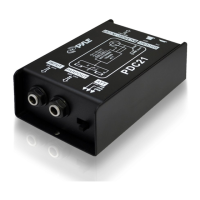
1. INPUT – 1/4” input connector.
2. PARA OUT – It’s parallel output 1/4” jack for passing the input
signal through to a stage amplifier or monitor system.
3. ATT Switch – input attenuation, switchable(0dB,-20dB,-40dB)
4. BALANCED OUTPUT – Male XLR connector.
5. GROUND – When engaged, the ground from the PDC21 chassis
detaches from the XLR jack.
Fr