pla1585
fuses
wiring tips
When making electrical connections to your amplifier, please observe the
following:
Use at least 8 gauge wire for power and ground connections.
Wire the amplifier directly to the car battery.
For the ground connection, use the shortest possible wire to a good chassis ground point.
Wire the Remote connection to the auto start lead of your head unit, equalizer or power antenna.
About power fuses:
Pyle Blue Wave Series amplifiers feature built-in fuse systems. These fuses protect both the
amplifier and the electrical system in your vehicle from fault conditions. If you ever need to
replace the fuse in your Pyle Blue Wave Series amp, use a fuse of exactly the same type and
rating. A different type or rating of fuse may result in damage or fire.
31
mounting
blue
wave
speaker connections
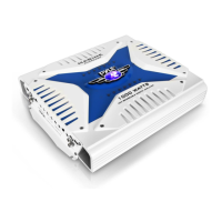
5 ch amp PLA1585
blue
wave
mounting and installation
PLA485•PLA785•PLA885•PLA1085•PLA1285•PLA1585
Your new Pyle Blue Wave Series amplifier comes complete with all required mounting hardware. When determining a suitable location in your vehicle for the amp, please remember
that it is a high-power electronic device capable of generating high heat.
For this reason, always choose a location in your vehicle which has low vibration, adequate ventilation, a minimum of dust, and no moisture. Be sure to mount
the amp in such a manner as to allow reasonable airflow over the cooling fins.
Mark the location for the mounting screw holes by positioning the amp where you wish to install it and use a scribe (or one of the mounting screws) inserted in each of
the mounting holes to mark the mounting surface. If the mounting surface is carpeted, measure the hole centers and mark with a felt tip pen.
Before attempting to drill the mounting holes, take note of any wires, lines or other devices in your vehicle which may be located behind the mounting
surface! Then drill pilot holes in the mounting surface for the mounting screws and insert them. Tighten the screws securely.
30
2 CH Bridged Output Mode with Subwoofer Output
MINIMUM
SPEAKER
IMPEDANCE
4 OHMS!
SUBWOOFER
L
R