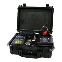
Operation
Figure 5 MP50 MP30 Use
Figure 6 MP50 MP30 Use
MP10
MP30
Maximum Point
of Drawdown
Normal
Static
Level
MP50
12
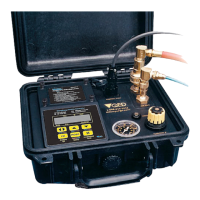
Controller to pump
connection
Compressed gas source
connection
Connector for optional
MP30 Drawdown Control
Flow throttle
Discharge cycle
indicator
psi
0
THROTTLE
CONTROL PORT
DISCHARGE CYCLE
AIR IN
AIR OUT
MicroPurge Basics Controller
MP Micro Purge
ID ID Time Set
MN Manual Time Set
LVL LevelShutoff
CYCLE
I I
MODE
CPM/Value Flow/Value Flow/Value
Hold/Sample
/Cycle
Start/Stop
ID/MN/MP/
Battery
Mode CPM
ID
Time
Refill
Discharge
00.1
103
10.0
MP CPM4 >05.0
D E
D E
1-800-624-2026
micropurge.com
O
U
E D
asics
CONTROLLER
MP10
MicroPurge Mode Quick Guide
3 AA BATTERIES INSIDE
MODEL
MicroPurge Mode Quick Guide
1. Opening cover turns power ON. (Close to turn OFF.)
2. Select desired Cycles Per Minute (CPM) with the key
(default value is 4 CPM).
3. Turn throttle to set depth on gauge to 10-20 feet
deeper than the pump location in the well.
4. Press CYCLE to START pumping.
5. When water discharge begins, adjust throttle until
a slow, steady flowstream is achieved.
6. Press keys to set the desired purge flow.
7. Use key to directly control sample flow and pause.
II